
Video generator - use of database for video, image, graphics and audio

a database and video technology, applied in the field of video generators, can solve the problems of difficult database searches to find matches, inability to directly compress data flow in a conventional sense, and large computing resources

Inactive Publication Date: 2014-06-12
GURULOGIC MICROSYST
View PDF1 Cites 8 Cited by
  • Summary
  • Abstract
  • Description
  • Claims
  • Application Information

AI Technical Summary

Benefits of technology

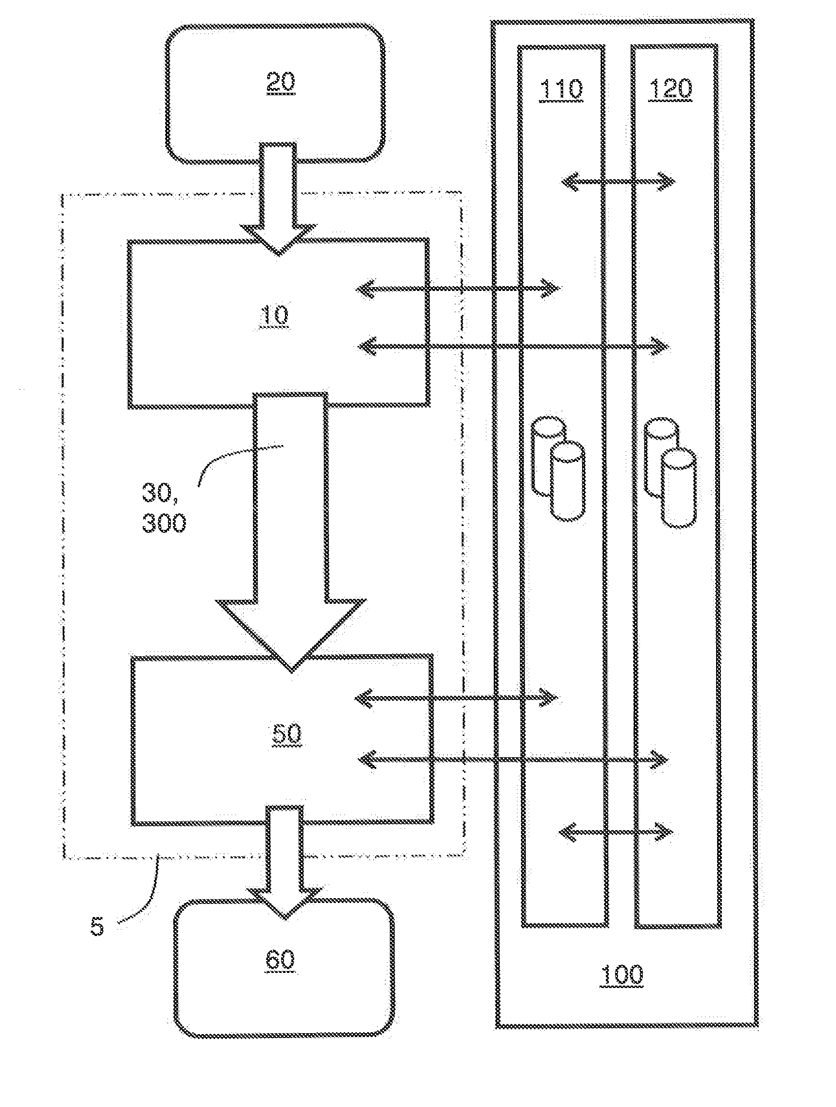
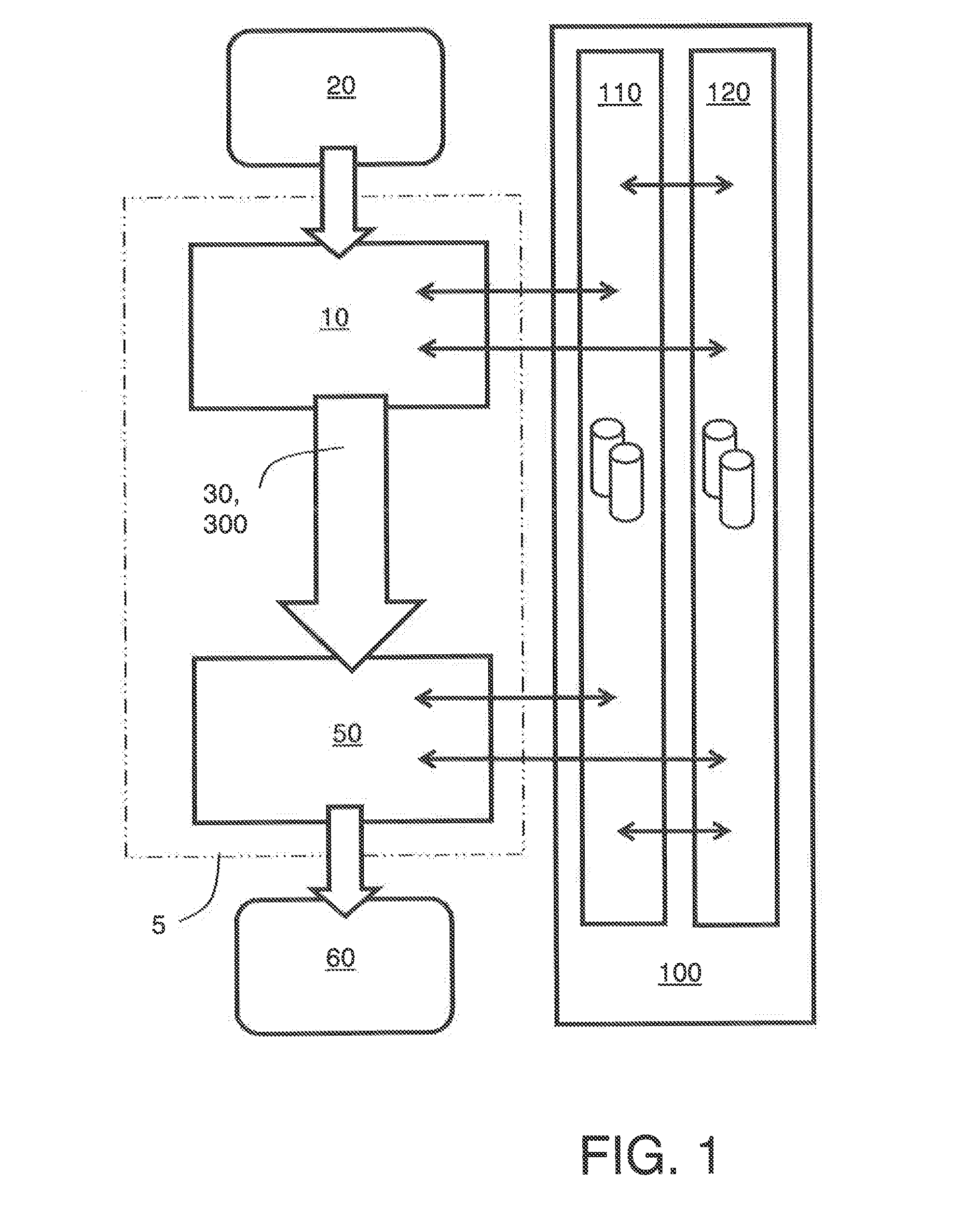
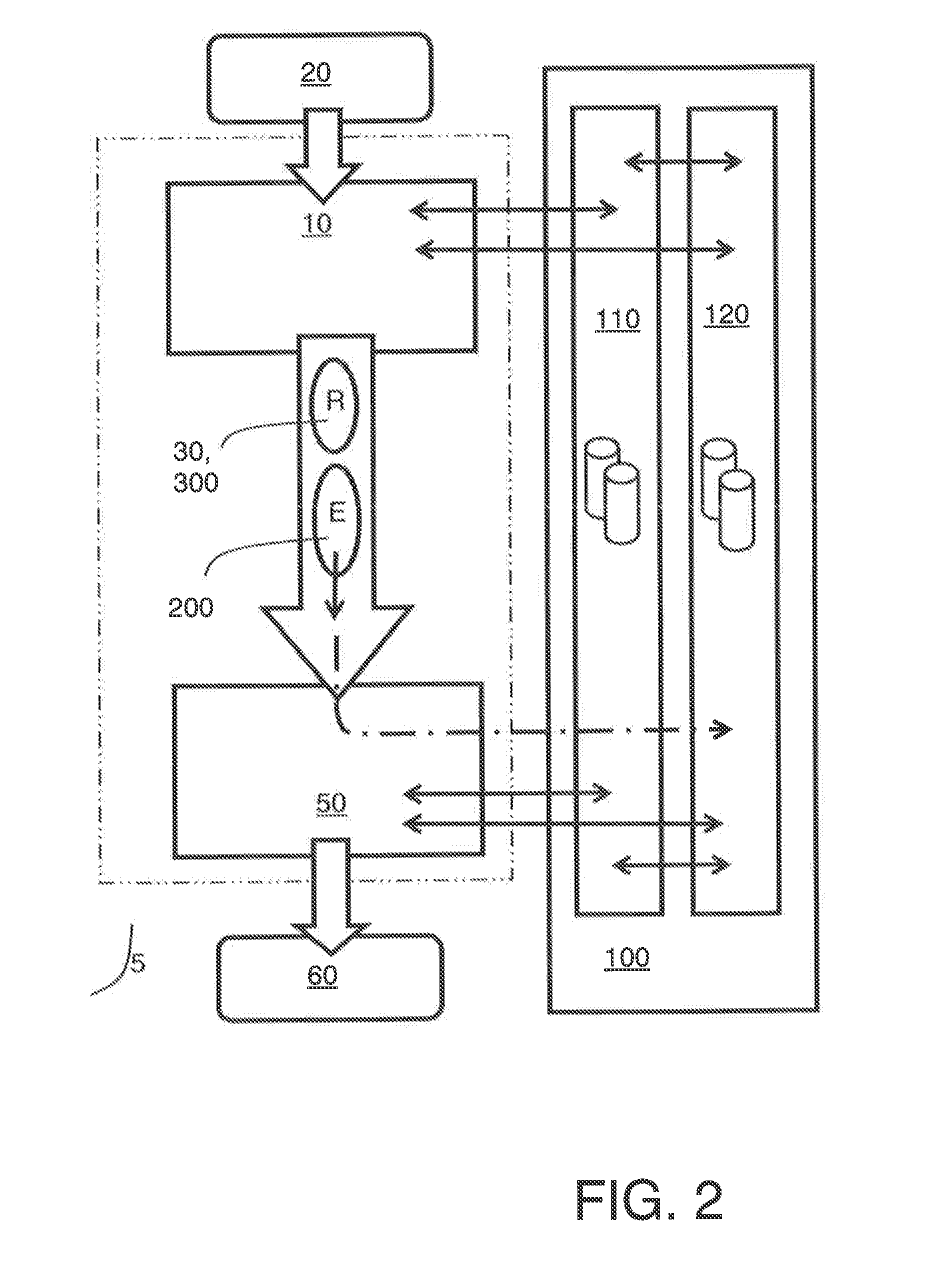
The present invention provides an improved method of encoding source data, as well as an encoder operable to implement this method. Additionally, the invention provides an improved method of decoding encoded data, resulting in superior video, image graphics, and audio decoded content quality. The use of fewer data bits to be communicated, decreased data size, and savings in computational resources, electrical power consumption, and data loading time are just a few benefits of the invention. The invention also allows for faster static database servers in client LAN's, thereby achieving more efficient data transfer. The encoder is also operable to restructure one or more of the databases as a function of the frequency of accessing elements for granting faster access to elements that are accessed more frequently.

Problems solved by technology

However, the method does not directly compress the data flow in a conventional sense.
However, on account of data in association with the database elements not having any connection with each other, performing searches in the database to find matches is difficult and requires considerable computing resources as the size of the database is increased.
Conversely, when the database is small, matching of the image blocks to the already existing blocks in the database is compromised, with a result that an image cannot be constructed from coded data generated by the method to a sufficient degree of quality.
Moreover, such increase in data being stored and transmitted requires increasingly more resources for hardware devices, for example more electrical power consumed for providing more processing capacity and larger communication transmission bandwidths.

Method used


Image

  • Video generator - use of database for video, image, graphics and audio
  • Video generator - use of database for video, image, graphics and audio
  • Video generator - use of database for video, image, graphics and audio

Examples


Embodiment Construction

[0105]When describing embodiments of the present invention in the following, abbreviations are employed as provided in Table 1:

TABLE 1details of acronyms employed to describe embodimentsAcronymDetail1D1-Dimensional, for example referring to a signal or data packet2D2-Dimensional, for example referring to a signal or data packet3D3-Dimensional, for example referring to a signal or data packetBlockMultiple data elements from digital data, namely a part of digital dataCRCCyclic redundancy checkCodecEncoder and decoder for digital dataDBDatabase in RAM-based or ROM-based memoryDCDC-component of an image, namely an image mean, corresponding toan average brightness and represents a lowest spatial frequencypresent in the imageDelta CodingDelta coding is a way of storing or transmitting data in a form ofdifferences between sequential data rather than complete data filesDCTDiscrete Cosine TransformISPInternal Switch ProviderLANLocal Area NetworkRAMRandom Access MemoryRDRate-DistortionRLERun-...


PUM


Abstract

A method of encoding source data to generate corresponding encoding data for transmission or storage is provided, wherein the method includes:(a) matching one or more portions of the source data to one or more elements in one or more databases, wherein the one or more elements are representative of corresponding one or more data blocks, and recording reference values which relate the one or more portions of the source data to the one or more matched elements; and(b) including the reference values in the encoded data together with the one or more databases and / or information identifying the one or more databases.A similar method of decoding encoded data to generate corresponding decoded output data is also provided is also described. The methods are beneficially implemented in an encoder, a decoder and in a codec.

Description

CROSS REFERENCE TO RELATED APPLICATIONS[0001]This application claims the benefit under 35 U.S.C. §119(a) and 37 CFR 1.55 to UK Patent Application No. 1222240.2, filed on Dec. 11, 2012, the entire content of which is hereby incorporated by reference.FIELD OF THE INVENTION[0002]The present invention relates to encoders for encoding source data for generating corresponding encoded data; moreover, the present invention relates to decoders for decoding the encoded data to generate corresponding decoded data representative of the source data; the encoders and the decodes are operable to employ one or more databases which include information which is processed in combination with the encoded data at the decoders for generating the decoded data. Moreover, the present invention concerns methods of encoding source data to generate corresponding encoded data; moreover the present invention concerns methods of decoding the encoded data for generating decoded data representative of the source da...

Claims


Application Information

Patent Timeline
IPC IPC(8): H04N7/26
CPCH04N19/00533H04N19/00H04N19/46H04N19/44H04N19/94H04N19/119H04N19/176G06T9/008H04N19/124H04N19/42H04N21/236H04N21/434G10L19/02
Inventor KARKKAINEN, TUOMASKALEVO, OSSI MIKAEL
Owner GURULOGIC MICROSYST
Learn More