
Energy storage system and method thereof

a technology of energy storage and energy storage system, applied in the direction of electric variable regulation, process and machine control, instruments, etc., can solve the problems of excessive ripple and oscillation, inability to maintain stable state,

Inactive Publication Date: 2014-05-22
SAMSUNG SDI CO LTD
View PDF9 Cites 1 Cited by
  • Summary
  • Abstract
  • Description
  • Claims
  • Application Information

AI Technical Summary

Benefits of technology

This patent describes an energy storage system that can quickly and accurately track the maximum power point of a nonlinear power generating system. It does this by adjusting the control variable in a way that increases or decreases the change in the controlled variable when the current and power slope of the system are outside of a predetermined range. This allows for efficient use of the system's power generation capabilities. The technical effect of this patent is a more reliable and efficient energy storage system that can maximize power generation.

Problems solved by technology

Due to such a phenomenon, an unstable state such as excessive ripple and oscillation may occur in a system during power conversion.

Method used


Image

  • Energy storage system and method thereof
  • Energy storage system and method thereof
  • Energy storage system and method thereof

Examples


Embodiment Construction

[0041]Example embodiments will now be described more fully hereinafter with reference to the accompanying drawings; however, they may be embodied in different forms and should not be construed as limited to the embodiments set forth herein. Rather, these embodiments are provided so that this disclosure will be thorough and complete, and will fully convey the scope of the disclosure to those skilled in the art.

[0042]Hereinafter, embodiments will be described in detail with reference to the accompanying drawings.

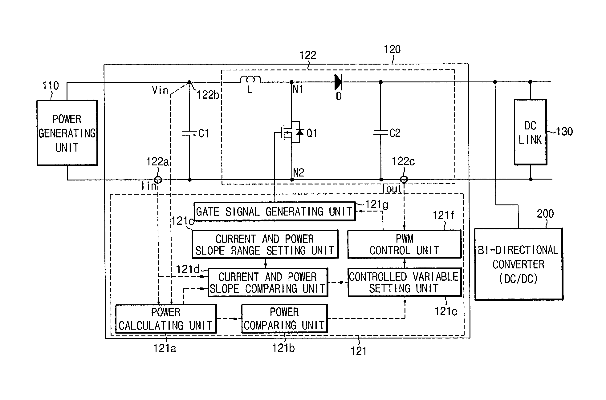
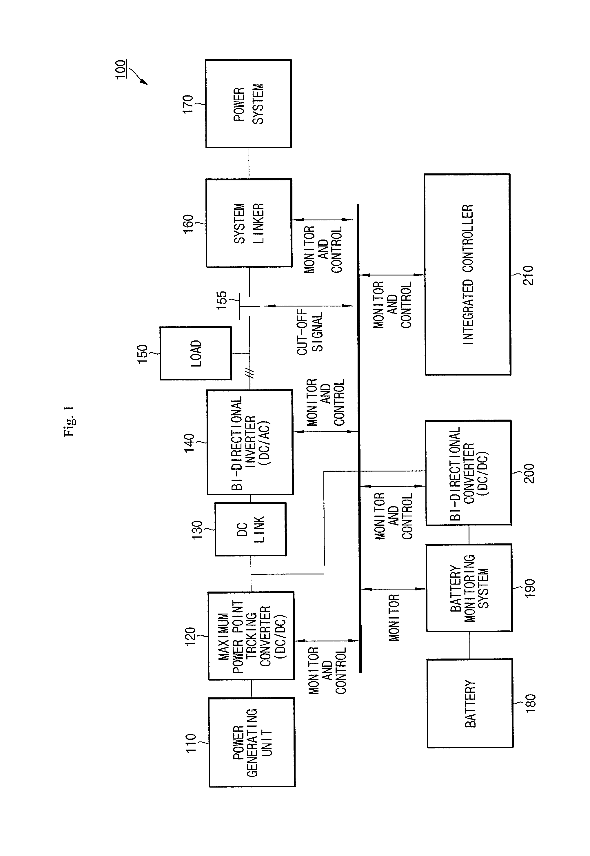
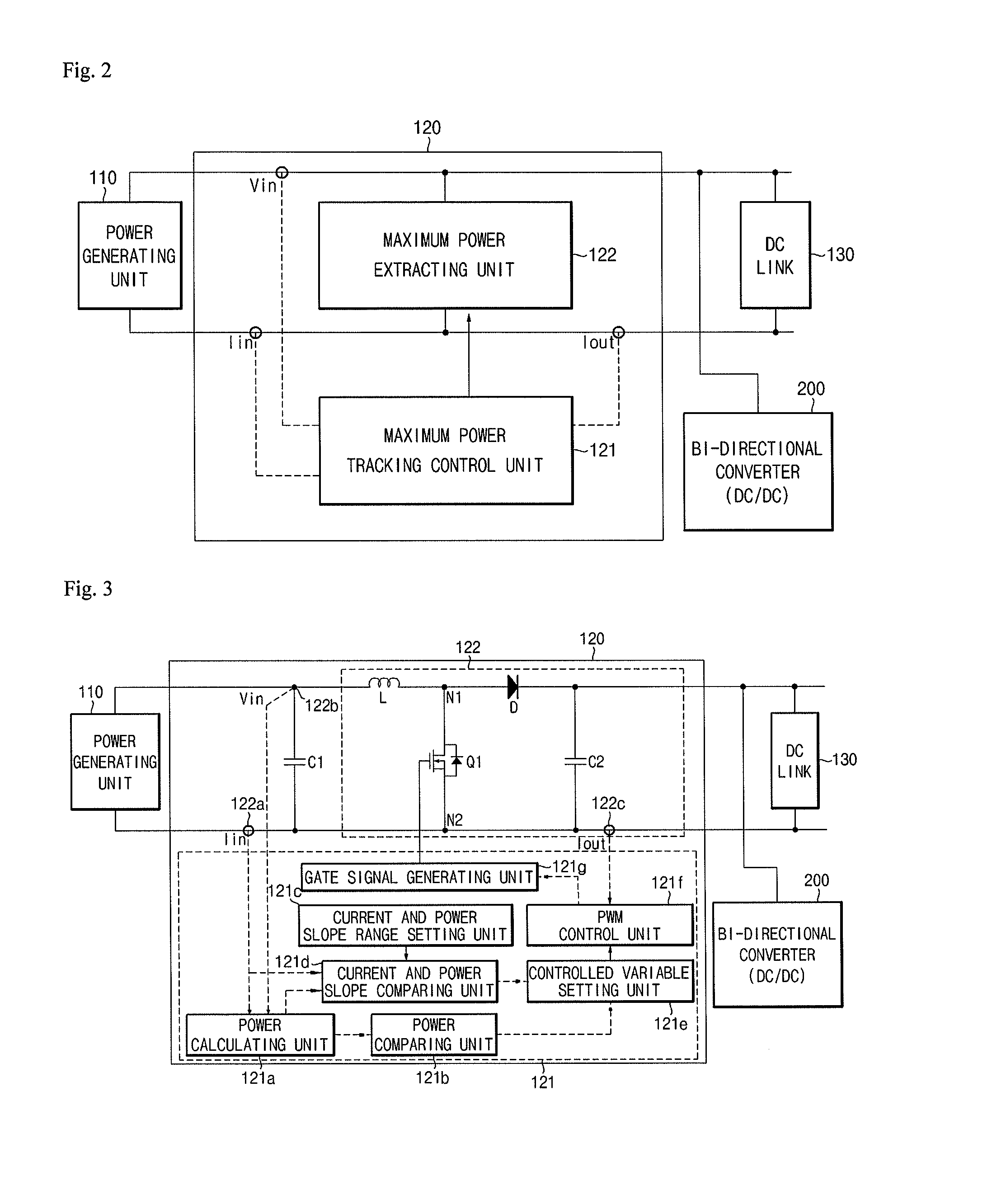
[0043]FIG. 1 illustrates a block diagram of a power generating system according to an embodiment. As shown in FIG. 1, a nonlinear power generating system 100 includes a power generating unit 110, an energy storage system (ESS) 120, a Direct Current (DC) link 130, a bi-directional inverter 140, a load 150, a system linker 160, a electric power system 170, a battery 180, a battery monitoring system 190, a bi-directional converter 200, and an integrated controller 210.

[0044]The p...


PUM


Abstract

An energy storage system (ESS) and a method thereof are disclosed. The system includes a maximum power tracking control unit changing a controlled variable for maximum power point extraction in proportion to an hourly current and power slope of the power generating unit, setting the change amount of the controlled variable to be relatively large if the hourly current and power slope is out of a predetermined hourly current and power slope range, and setting the change amount of the controlled variable to be relatively small if the hourly current and power slope is within a predetermined hourly current and power slope range, and a maximum power extracting unit extracting and converting a maximum power from the power generating unit in response to a control of the maximum power tracking control unit.

Description

CROSS-REFERENCE TO RELATED APPLICATION[0001]The present application claims priority under 35 U.S.C. §119 to Korean Patent Application No. 10-2012-0133284, filed on Nov. 22, 2012, in the Korean Intellectual Property Office, and entitled: “Maximum Power Point Tracking Converter and Method Thereof,” which is incorporated by reference herein in its entirety.BACKGROUND[0002]1. Field[0003]Embodiments relate to an energy storage system (ESS) and a method thereof.[0004]2. Description of the Related Art[0005]In general, an electrical energy source (for example, an electrochemical battery and generator) has characteristics of a linear voltage source, and thus, always maintains a constant voltage regardless of characteristics of a load. Additionally, since there is only one operating point in such an electrical energy source, it always operates as a stable system under any input and output condition. That is, when an electrical energy source with a linear voltage source is used, desired operat...

Claims


Application Information

Patent Timeline
Patent Type & Authority Applications(United States)
IPC IPC(8): H02M3/156
CPCG05F1/67H02M3/3376H02M3/156H02J2300/26H02J3/381Y02E10/56H02S40/30Y02E10/76
Inventor CHO, SUNGCHUN
Owner SAMSUNG SDI CO LTD
Learn More