
Brake monitoring systems and methods

a technology for monitoring systems and brakes, applied in braking systems, analogue processes for specific applications, instruments, etc., can solve problems such as insufficient air braking capability, cylinders may become stuck and not actuate properly, and air brake systems may be subject to numerous modes of failure,

Active Publication Date: 2014-05-15
GE GLOBAL SOURCING LLC
View PDF2 Cites 8 Cited by
  • Summary
  • Abstract
  • Description
  • Claims
  • Application Information

AI Technical Summary

Benefits of technology

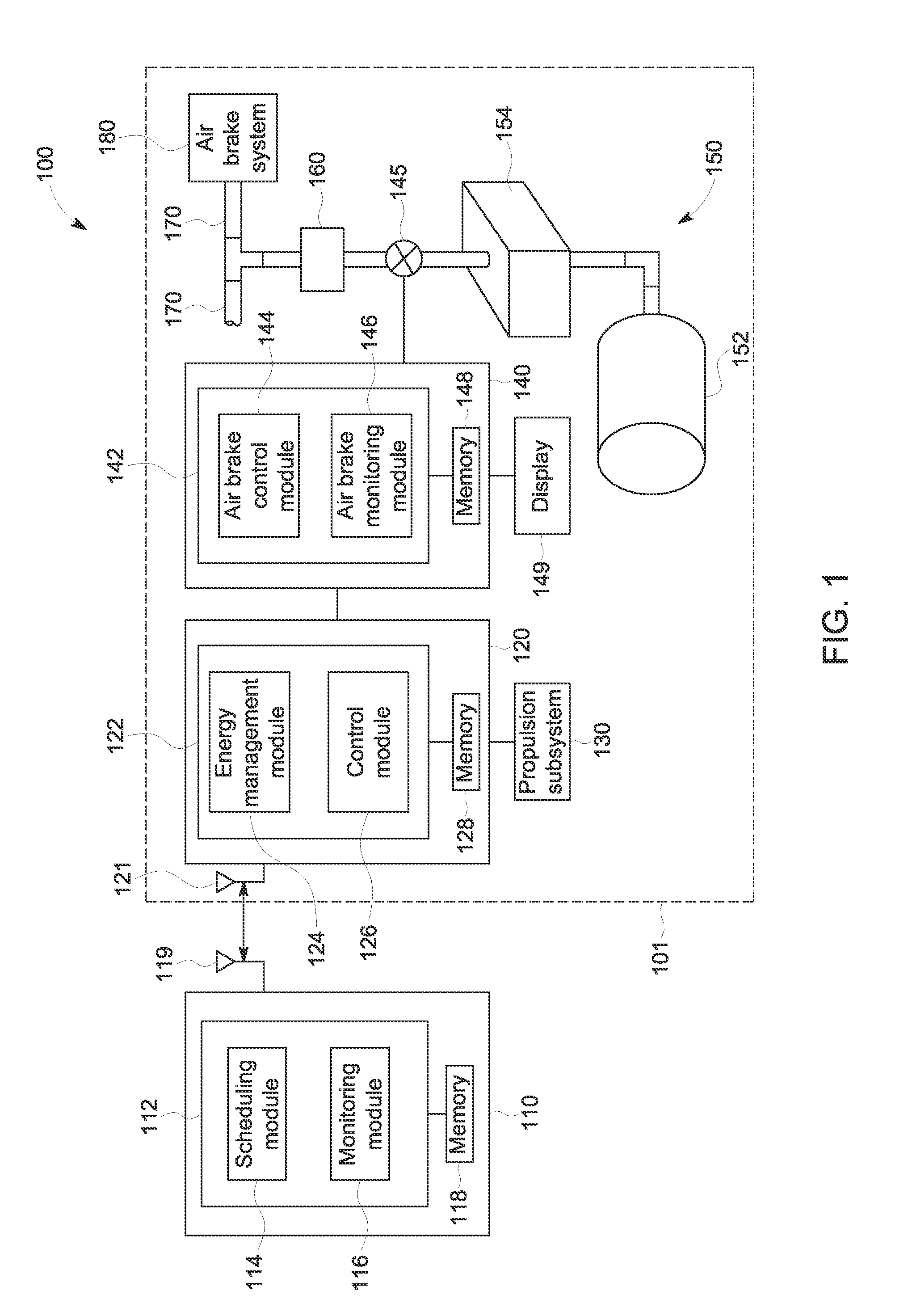
The patent describes a system for controlling and monitoring air brakes on vehicles. The system includes an air brake control module that controls the pressure in the brake pipes to activate the brakes, an air flow detector that measures air flow through the brake pipes, and an air brake monitoring module that obtains a reference volume of air used to recharge the braking system when the brakes are first applied, and compares it to the actual volume of air used after a braking activity. The system can also use information from the air flow detector to obtain the actual volume of air used. The technical effects of the system include improved control and monitoring of air brakes, as well as improved safety and efficiency of the vehicle's braking system.

Problems solved by technology

However, air brake systems may be subject to numerous modes of failure, especially in the conditions encountered by traveling vehicles.
For example, couplings used in an air circuit (such as to connect portions of a brake pipe for supplying air to the individual pistons and associated reservoirs) may fail, cylinders may become stuck and not actuate properly, and the like.
If enough failures occur throughout the system, then an insufficient amount of air braking capability may be present at an emergency.
The stopping of the train and inspection of the brakes is a time consuming operation, adding to the time and expense of missions, particularly longer missions that may require multiple stops and brake inspections.
Such electronic controls, however, have several drawbacks.
For example, certain individual brakes may be able to communicate with the central processor but not be functional.
Further, electronic control systems may be quite expensive.

Method used


Image

  • Brake monitoring systems and methods
  • Brake monitoring systems and methods
  • Brake monitoring systems and methods

Examples


Embodiment Construction

[0018]One or more embodiments of the inventive subject matter described herein provide systems and / or methods for monitoring air brakes of a vehicle system. For example, embodiments use precision air flow meters and associated processing units and software to measure the flow of air during a recharging of an air brake system, and to determine a replenishment volume of air for the recharging, such as by integrating a measured or determined amount of flow rate. This replenishment volume may be compared to a reference replenishment volume measured and determined during an initial (e.g., previous) test braking application. Lower replenishment volume indicates a higher percentage of individual brakes that did not use their reservoir of available air (and thus those reservoirs were not required to be recharged), thereby indicating malfunction(s) of a portion of the air braking system. Further, the shape of the recharge flow curve may be used to determine a characteristic of the recharge, ...


PUM


Abstract

An air brake monitoring system includes an air brake control module and an air brake monitoring module. The air brake control module is configured to control variation of an amount of pressure in a brake pipe of the vehicle to actuate brakes of a braking system of the vehicle. The air brake monitoring module is configured to obtain a reference replenishment volume corresponding to a volume of air used to recharge the braking system after application of the brakes of the braking system when the braking system when a first amount of brakes are operational, to obtain an actual replenishment volume corresponding to an actual volume of air used to recharge the braking system of the vehicle after a braking activity performed by the vehicle, and to generate a signal based on a comparison of the actual replenishment volume to the reference replenishment volume.

Description

FIELD[0001]Embodiments of the subject matter described herein relate to brake monitoring systems and methods for vehicles.BACKGROUND[0002]A vehicle, such as a train, may use different types of brakes for stopping or slowing the vehicle. For example, a train having a plurality of cars may have a regenerative (or dynamic) braking system on powered units, and may also have an air brake system on some or all of the non-powered and powered units. The air brake system may provide air from one or more generally large reservoirs to generally smaller individual reservoirs associated with a piston for actuating one or more brake shoes against one or more wheels. While the regenerative braking system may be used more often than the air brake system, the air brake system may be intended to be employed during emergency situations or when supplemental braking in addition to the regenerative braking system is needed (for example, on a steep grade). Thus, it is important that the air brake system w...

Claims


Application Information

Patent Timeline
IPC IPC(8): B60T17/22
CPCB60T17/22B60T13/662B60T13/683
Inventor PELTZ, DAVID MICHAELMCMANUS, BRIAN JOSEPH
Owner GE GLOBAL SOURCING LLC
Learn More