
Luminescent material particles comprising a coating and lighting unit comprising such luminescent material

a technology of luminescent materials and particles, which is applied in the direction of discharge tubes/lamp details, discharge tubes luminescnet screens, disinfection, etc., can solve the problems of discharge efficiency and other problems, and achieve the effects of reducing ignition voltage, enhancing lifetime, and reducing the ion induced secondary electron emission coefficien

Inactive Publication Date: 2014-05-15
SIGNIFY HLDG BV
View PDF3 Cites 10 Cited by
  • Summary
  • Abstract
  • Description
  • Claims
  • Application Information

AI Technical Summary

Benefits of technology

This patent describes a new way to improve the stability of luminescent materials, especially UV emitting materials, by coating them with a special multi-layer coating. This coating consists of two layers: a first layer of aluminum oxide, and a second layer of magnesium oxide. This new coating makes the particles of the luminescent material more resistant to damage caused by the discharge process in lamps, leading to longer lifetime and higher photoluminescence quantum yield. This patent also introduces a new method for reducing staining and maintaining the brightness of the phosphor particles.

Problems solved by technology

Other emission wavelengths were achieved by using a XeBr* (282 nm), XeCl (308 nm), or KrCl* (222 nm) excimers, however, this goes at the cost of discharge efficiency.

Method used


Image

  • Luminescent material particles comprising a coating and lighting unit comprising such luminescent material
  • Luminescent material particles comprising a coating and lighting unit comprising such luminescent material
  • Luminescent material particles comprising a coating and lighting unit comprising such luminescent material

Examples


Embodiment Construction

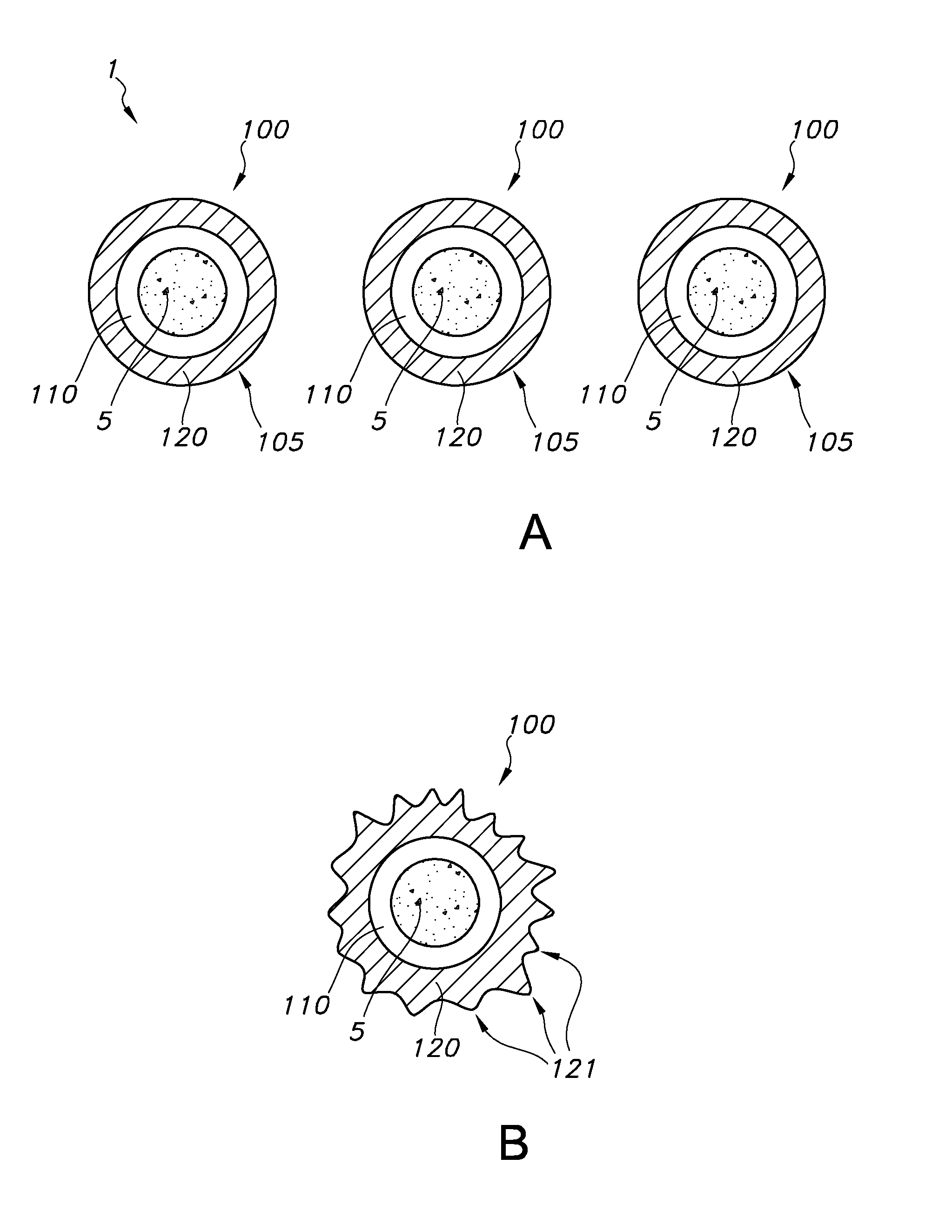
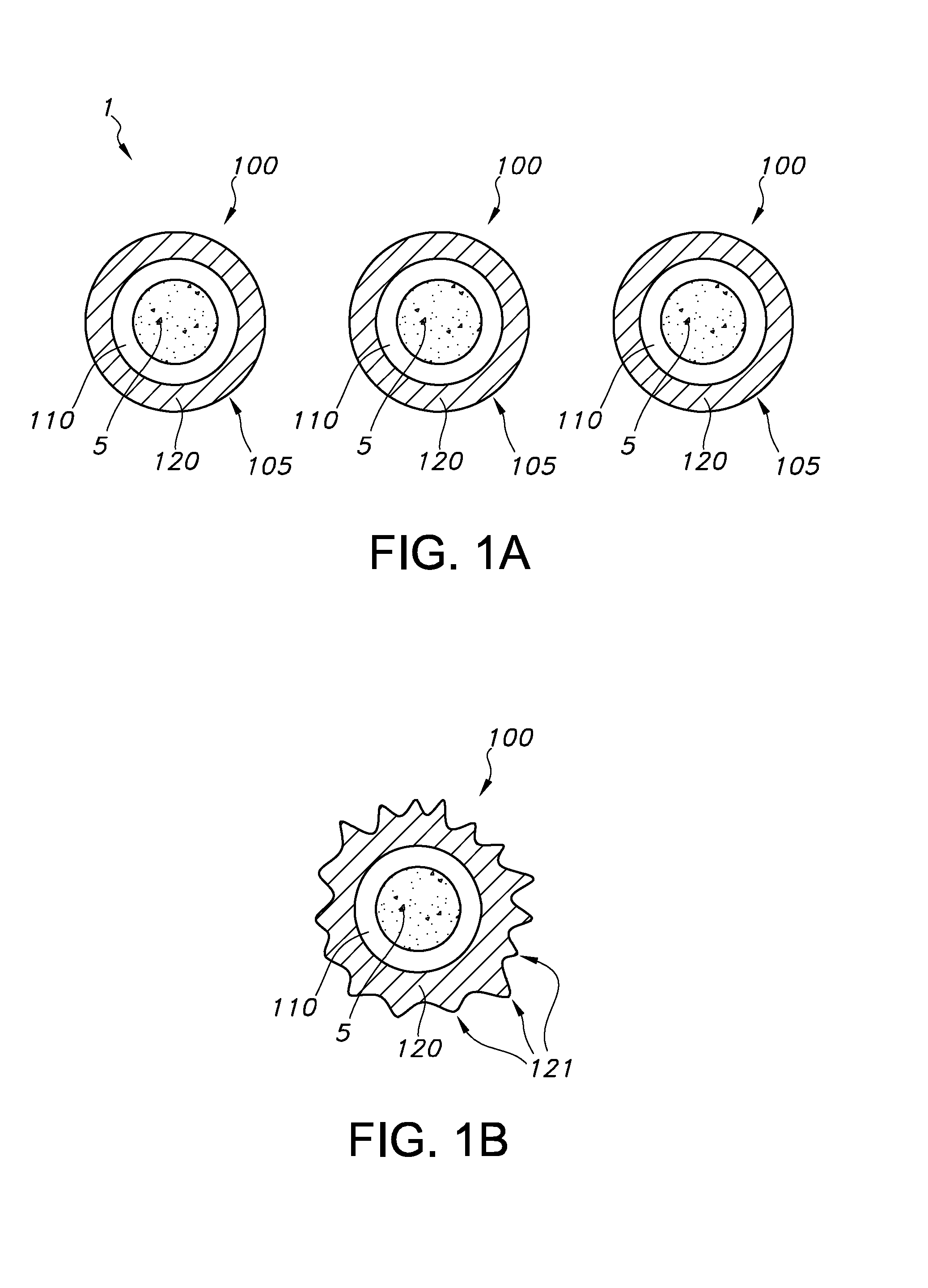
[0039]FIG. 1a schematically depicts luminescent material 1, which, by way of example is symbolized by three particles 100. The particles 100 of the luminescent material comprises a core of UV-luminescent material, indicated with reference 5, and at least a first coating layer 110 and a second coating layer 120, with the latter being more remote from the UV luminescent material 5 than the former. In this schematic embodiment, the first coating layer 120 is applied to the core of UV luminescent material 5, and the second coating 120 is applied to the first coating layer 110. The (multi-layer) coating, here a bi-layer coating, is indicated with reference 105. Because of the multi-layer aspect of the coating 105, the coating is herein also indicated as “onion-shell type coating”.

[0040]As indicated above, especially advantageous is that coating layers 120, like MgO coatings, on the first coating layer 110, may appear to have extending structures, indicated with reference 121. Such struct...


PUM


Abstract

The invention provides a a luminescent material comprising particles of UV-luminescent material having a coating, wherein the coating (a “multi-layer coating”) comprises a first coating layer and a second coating layer, wherein the first coating layer is between the luminescent material and the second coating layer, and wherein in a specific embodiment the second coating layer comprises an alkaline earth oxide, especially MgO. Further, the invention provides a lighting unit comprising such luminescent material.

Description

FIELD OF THE INVENTION[0001]The invention relates to a luminescent material particles comprising a coating and lighting unit comprising such luminescent materialBACKGROUND OF THE INVENTION[0002]Dielectric barrier discharge lamps with protective coatings are known in the art. WO2006072893, for instance, describes a system incorporating a DBD lamp, a dielectric barrier discharge (DBD-) lamp, and a phosphor coating for use as luminescent coating in a dielectric barrier discharge (DBD-) lamp, especially in a mercury-free DBD-lamp, comprising several phosphor grains together forming a luminescent coating layer for converting a primary discharge radiation into a wanted radiation, whereby the phosphor coating comprises a protective coating layer at least partly surrounding the luminescent coating layer for minimizing degradation of the luminescent coating layer during use in a DBD-lamp.[0003]Further, also coatings on luminescent material particles are known in the art. U.S. Pat. No. 5,051,...

Claims


Application Information

Patent Timeline
IPC IPC(8): C09K11/02H01J61/44
CPCH01J61/44C09K11/025C09K11/7701C09K11/7709C09K11/7713C09K11/772C09K11/7738C09K11/7741C09K11/7777C09K11/778
Inventor GREUEL, GEORGJUESTEL, THOMASKUC, JAGODA MAGDALENA
Owner SIGNIFY HLDG BV
Learn More