Dilatation system for a medical device

Inactive Publication Date: 2014-05-08
GUERRA ROMANO
View PDF4 Cites 4 Cited by
  • Summary
  • Abstract
  • Description
  • Claims
  • Application Information

AI Technical Summary

Benefits of technology

The present invention provides a dilatation system for a medical device comprising a tubular portion and a dilating balloon at the distal end of the tubular portion. The invention includes an insertion element to prevent skin or tissue to be trapped between the distal end of the tubular portion and the proximal end of the inflated balloon. The new system facilitates introduction of the tracheostomy tube, avoiding problems with the patient's skin and the balloon while it is being inflated.

Problems solved by technology

All of this requires the involvement of a team of surgeons, a sterilized environment and complicated arrangements which are not always easy to obtain in emergency situations.
The disadvantages of this technique are the long sequence of manipulations, a significant manual effort, and the potential damage to the posterior wall of the trachea from friction with dilators during the insertion phase.
This method is more traumatic than the previous ones, with a higher incidence of complications, including frequent rupture of the tracheal rings.
The limits of this system are most evident between the dilating and insertion stages, when a gaping opening is created, entailing possible bleeding from tissues or difficulty with introducing the tube due to tissue recoil.
The risk is therefore that force must be applied to force the tube forward, thereby causing trauma and tissue damage to the insertion point.

Method used


Image

  • Dilatation system for a medical device
  • Dilatation system for a medical device
  • Dilatation system for a medical device

Examples


example of application

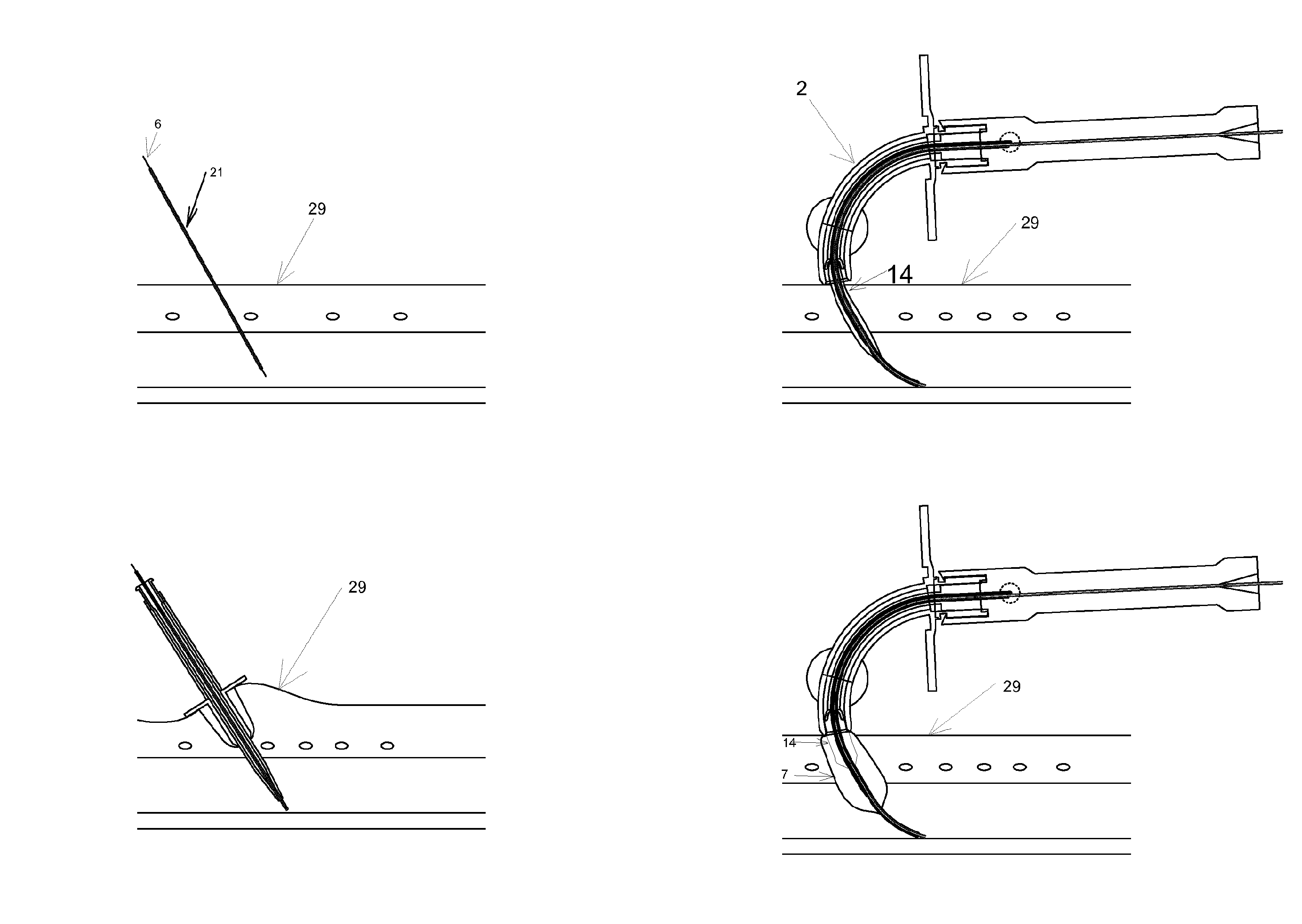
[0074]As illustrated by FIGS. 4A to 4F, an example of a tracheostomy procedure using the dilatation system according to the invention involves:

[0075]a) positioning of a needle (21)or needle cannula, preferably between the second and third tracheal rings, sufficiently large to allow a guide wire (6) to pass though;

[0076]b) insertion of a flexible metal guide wire (6) through the needle. The needle is then removed, leaving the wire (6) in place for its use as a guide in subsequent steps;

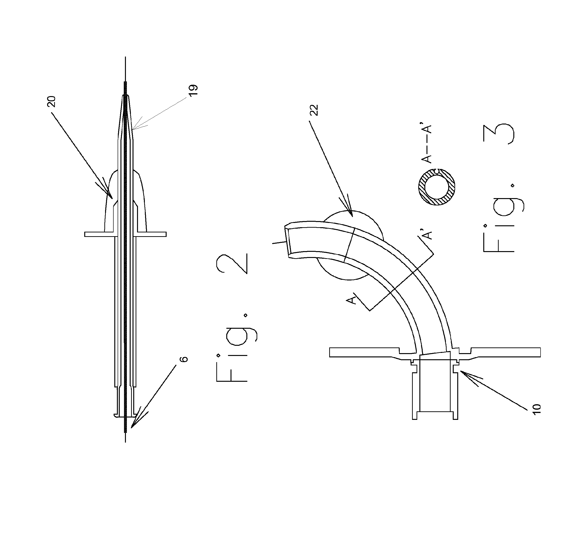
[0077]c) insertion of the dilator with scalpel blades (20) to create a gap large enough for insertion of the deflated dilating balloon (7);

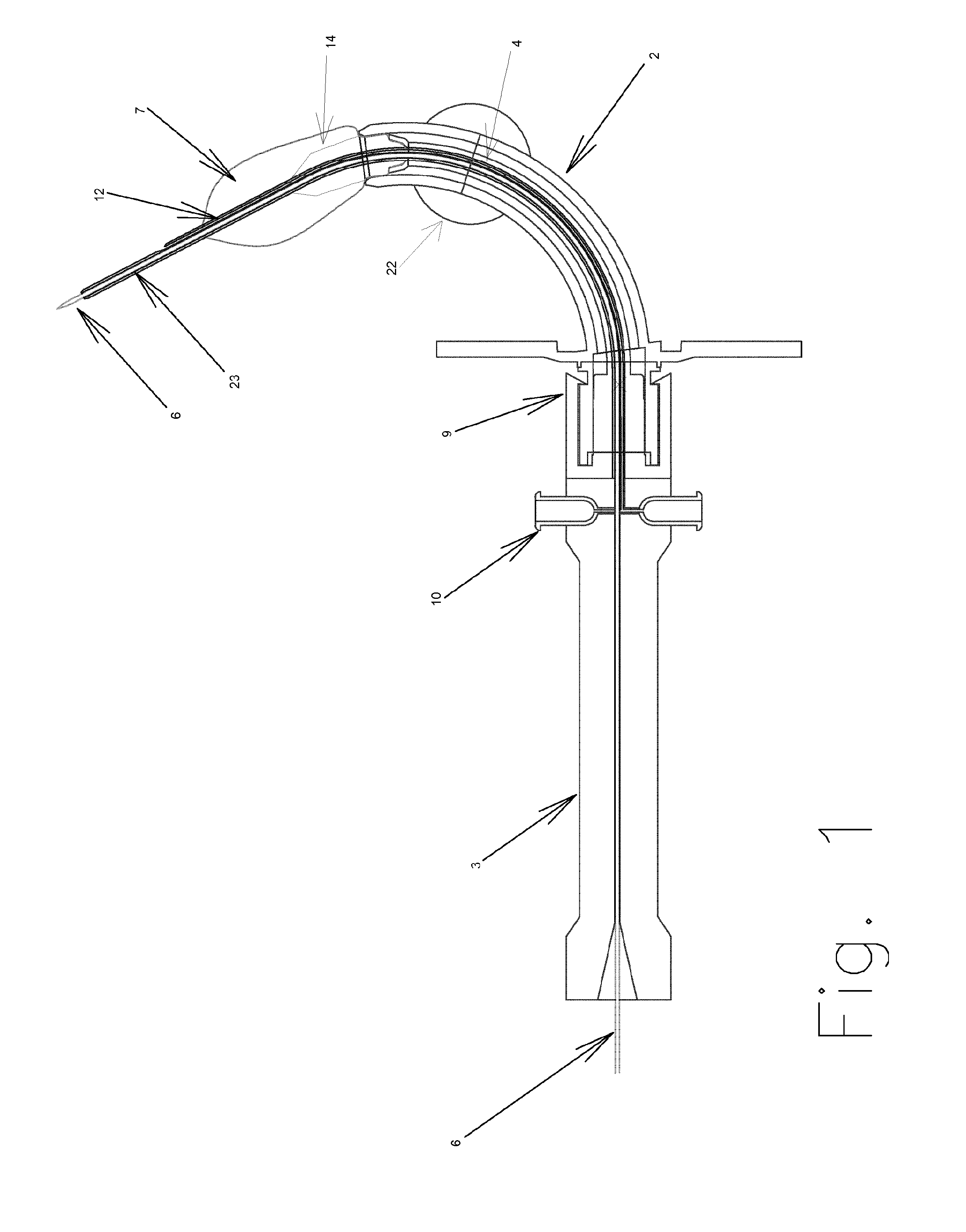
[0078]d) insertion along the guide wire (6)of the surgical device (1) fitted with a tracheostomy tube (2) secured to the handle (3). The deflated and well lubricated dilating balloon (7) of the device (1) is pushed towards the tracheal wall as far as the tip of the cone (14) inside the balloon (7);

[0079]f) inflation of the dilating balloon (7) ensures dilatation of ...


PUM


Abstract

The present invention relates to a dilatation system for a medical device, in particular where the insertion of a tubular structure (e.g. cannula, catheter or drainage tube) is required. The dilatation system is ideally used for tracheostomy procedures, such as Percutaneous Dilating Tracheostomy (PDT). This minimally invasive surgical device enables to open a gap between the first tracheal rings and to introduce a tracheostomy tube in the trachea of a patient. The present invention also relates to a method inserting a tubular structure into a patient for example a tracheostomy tube in the trachea of a patient.

Description

[0001]The present invention relates to a dilatation system for a medical device, in particular where the insertion of a tubular structure (e.g. cannula, catheter or drainage tube) is required. The dilatation system is ideally used for tracheostomy procedures, such as Percutaneous Dilating Tracheostomy (PDT). This minimally invasive surgical device enables to open a gap between the first tracheal rings and to introduce a tracheostomy tube in the trachea of a patient. The present invention also relates to a method inserting a tubular structure into a patient for example a tracheostomy tube in the trachea of a patient.BACKGROUND[0002]Classical surgical tracheostomy is still the oldest and most frequently used procedure. The procedure consists of making a surgical gap between the rings of the trachea by using traumatic surgical instruments like scalpels, lancets and dilating pincers. All of this requires the involvement of a team of surgeons, a sterilized environment and complicated arr...

Claims


Application Information

Patent Timeline
IPC IPC(8): A61M16/04A61B17/34
CPCA61B17/3415A61M16/0465A61M16/04A61M16/0472A61M29/02A61M16/0434A61B2017/320048A61M16/0459A61M16/0447
Inventor GUERRA, ROMANOALBALAT, ALBERTO
Owner GUERRA ROMANO
Why Eureka
Try Eureka