
Downhole pump assembly

a pump assembly and pump technology, applied in the direction of fluid removal, positive displacement liquid engine, borehole/well accessories, etc., can solve the problems of double financial expenses, two tubing strings, two rod drives, and two tubing strings running operations entail great labor consumption, so as to increase the overhaul period and improve the reliability of operation

Inactive Publication Date: 2014-05-01
GABDULLIN RIVENER MUSAVIROVICH
View PDF16 Cites 4 Cited by
  • Summary
  • Abstract
  • Description
  • Claims
  • Application Information

AI Technical Summary

Benefits of technology

The proposed downhole pump assembly allows for enhanced operation reliability and increased overhaul period using only one conventional pumping unit, one tubing string, and one rod string with standard oil-well plunger pumps. Additionally, it allows for the operation of two or three reservoirs if the well serves as a tubing string. The advantages of the assembly include improved performance and flexibility.

Problems solved by technology

Running operations of two tubing strings entail great labor consumption, processing complexity and losses of time.
Moreover the use of two pumping units, two tubing strings, two rod drives, and an anchor doubles financial expenses.

Method used


Image

  • Downhole pump assembly
  • Downhole pump assembly
  • Downhole pump assembly

Examples


Embodiment Construction

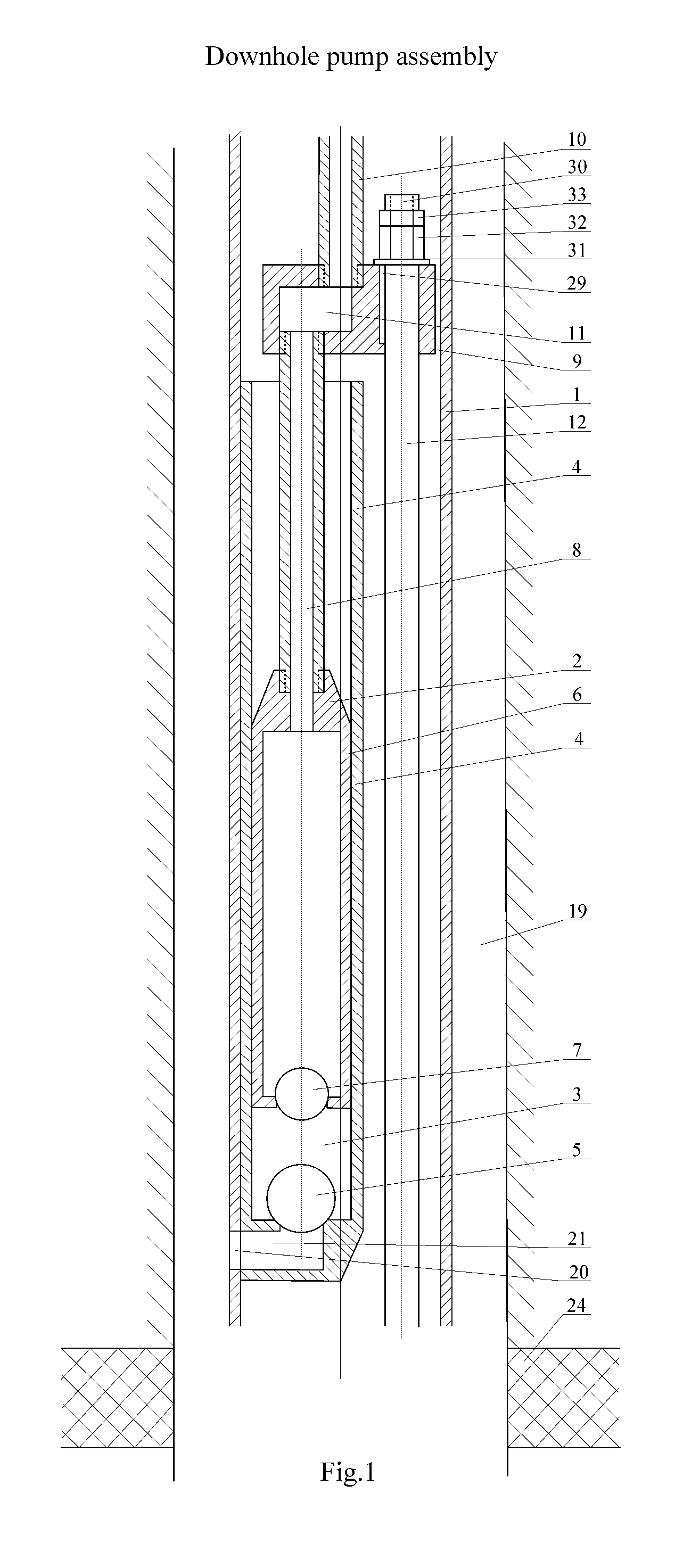
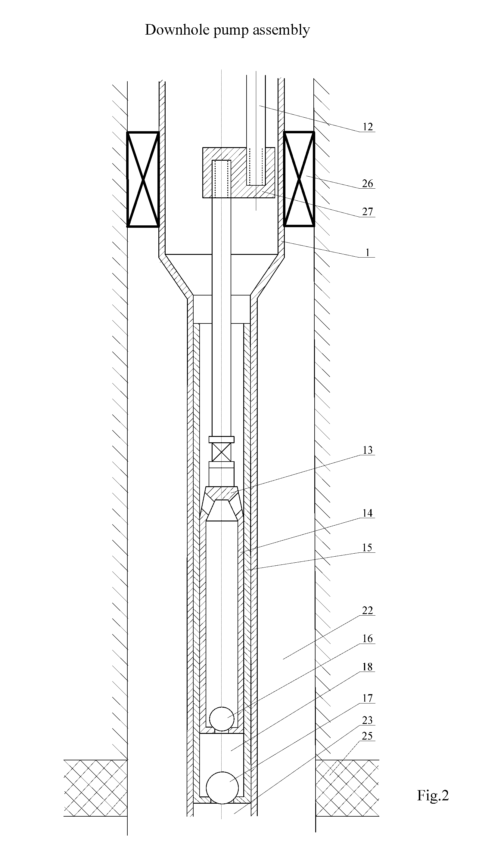
[0018]The innovative downhole pump assembly consists of a body 1, an upper oil-well sucker-rod pump 2 containing a pump chamber 3 in a cylinder 4 with a suction valve 5 and a hollow plunger 6 with an discharge valve 7 in its lower part. The plunger 6 is connected with a hollow rod string 8 through a crossbar 9 with a joint hollow rod string 10. The axis of the upper oil-well sucker-rod pump 2 is biased from the axis of the downhole pump assembly body 1. In the crossbar 9 there is a channel 11 which connects the chamber of the plunger 6 with the chamber of the joint hollow rod string 10 (FIG. 1). Moreover, the crossbar 9 is connected with an upper end of the rod string 12 of a lower oil-well sucker-rod pump 13 (FIG. 2) the lower end of which, in turn, is connected with a made hollow plunger 14 of the lower oil-well sucker-rod pump 13. The rod string 12 is in the moon-shaped chamber formed by the outside surface of the upper oil-well sucker-rod pump 2 and the inner surface of the body...


PUM


Abstract

The invention pertains to oil production pumping equipment in particular to submersible downhole pumps with rod drives to simultaneously and separately lift reservoir fluids to the surface from two reservoirs of a single well. The downhole pump assembly comprises a drive, upper and lower oil-well sucker-rod pumps each connected with its own rod string. In addition to this the unit is equipped with the body, crossbar and joint hollow rod string the latter being attached to the upper part of the crossbar to the bottom of which the rod strings of the upper and lower oil-well sucker-rod pumps are fixed, moreover, the rod string of the upper oil-well sucker-rod pump being made hollow and interconnected with the hollow plunger of the upper oil-well sucker-rod pump and the channel in the crossbar with the joint hollow rod string, and the rod string of the lower oil-well sucker-rod pump is installed between the cylinder of the upper oil-well sucker-rod pump and the downhole pump assembly body, moreover, the upper oil-well sucker-rod pump being offset from the longitudinal downhole pump assembly body axis. Coaxiality of the lower oil-well sucker-rod pump is achieved through the use of the rod crossover shoe, S-shaped rod and non-central pipe sub. The lower plunger pump rod has a shaped cross-section. As a result a standard pumping unit and two oil-well sucker-rod pumps are used and both enhanced reliability of the downhole pump assembly and increased overhaul life of its operation are achieved.

Description

FIELD OF THE INVENTION[0001]The invention pertains to oil production pumping equipment. More specifically it relates to submersible downhole pumps used for extraction of formation fluids from deep wells operating in the conditions of simultaneous stage development.BACKGROUND OF THE INVENTION[0002]In view of technical benefits and results achieved the invention is most close to a downhole pump assembly used for simultaneous stage development from two formations. It includes a conventional pumping unit, a tubing string, an oil-well sucker-rod pump, a packer, a liner, an auxiliary conventional pumping unit and short tubing string installed at the depth above the upper formation, and a parallel anchor mounted on both tubing strings and above the upper formation, the short tubing string being equipped with another oil-well sucker-rod pump (RU 49895 U1, Oct. 12, 2005). The known equipment is to contain two conventional pumping units, two rod drives, and also two tubing strings, and an anc...

Claims


Application Information

Patent Timeline
Patent Type & Authority Applications(United States)
IPC IPC(8): F04B23/06F04B47/00
CPCF04B47/02E21B43/126F04B47/00F04B23/06F04B47/026
Inventor GABDULLIN, RIVENER MUSAVIROVICH
Owner GABDULLIN RIVENER MUSAVIROVICH
Learn More