
Time reversal optical tomography for locating targets in a highly scattering turbid medium

a time-reversal optical tomography and highly scattering technology, applied in the field of time-reversal optical tomography for locating targets in a highly scattering turbid medium, can solve the problems of poor signal-to-noise ratio, difficult to develop reliable and fast approaches, and loss of phase coherence and polarization, etc., to achieve the solution of the eigenvalue problem, the effect of less computation time and high resolution

Inactive Publication Date: 2014-04-24
RES FOUND THE CITY UNIV OF NEW YORK
View PDF1 Cites 19 Cited by
  • Summary
  • Abstract
  • Description
  • Claims
  • Application Information

AI Technical Summary

Benefits of technology

The patent discusses a new method called TROT for finding the location of targets in a sample. The method has several advantages over other methods. First, the size of the matrix used in TROT is smaller, making the solution of the inverse problem faster and easier. Second, the TROT approach runs a program over all voxels only once, without needing an iterative process, which saves computing time and avoids the issue of ill-posed solutions. In simulated data, TROT accurately locates target positions with high resolution, even in the presence of significant noise. Overall, the method can be useful for both simulations and experiments.

Problems solved by technology

Optical imaging of targets embedded in a highly scattering turbid medium, such as, a tumor in a breast, is a challenging problem because light is strongly absorbed and scattered by the medium leading to poor signal-to-noise ratio, as well as, loss of phase coherence and polarization.
IIR is an ill-posed problem and the development of reliable and fast approaches remains a formidable task.
Recent HR algorithms, such as Newton-Raphson-Marquardt algorithms and direct linear inversion of 3-D matrices, are time consuming.

Method used


Image

  • Time reversal optical tomography for locating targets in a highly scattering turbid medium
  • Time reversal optical tomography for locating targets in a highly scattering turbid medium
  • Time reversal optical tomography for locating targets in a highly scattering turbid medium

Examples


example 1

Testing TROT with Simulated Data

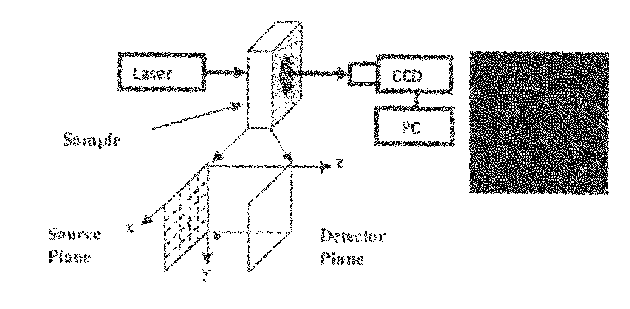
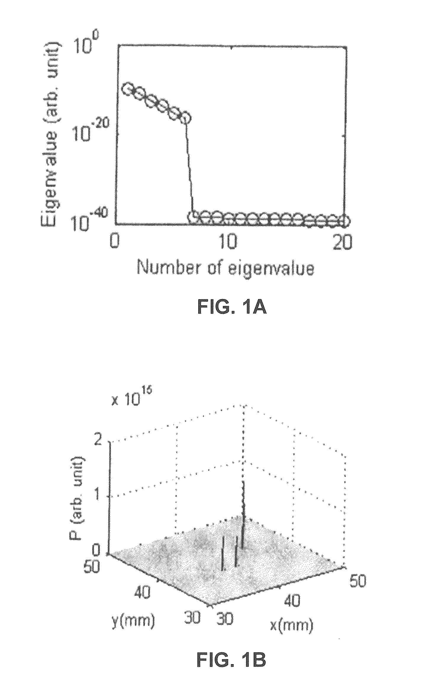
[0058]To test the efficacy of the TROT approach, we first consider a rather challenging task of detecting and locating six targets embedded in a simulated sample which is a 40-mm thick uniform scattering slab. Its absorption and diffusion coefficients are μa=1 / 300 mm−1 and D=1 / 3 mm, respectively. The incident CW beam was step-scanned in an x-y array of 41×41 grid points with a step size of 2 mm on the input plane covering an 80 mm×80 mm area. Light transmitted from the opposite side (output plane) was recorded at 41×41 grid points covering the same area. No random noise was added.

[0059]The six (M=6) point-like absorptive targets, with absorption coefficient difference of =0.01 mm from the background, were placed at A (24 mm, 26 mm, 9 mm), B (38 mm, 38 nam, 15 mm), C (38 mm, 38 mm, 21 mm), D (40 mm, 38 mm, 21 mm), E (44 mm, 42 mm, 21 mm) and F (30 mm, 30 mm, 31 mm), respectively. The origin (0 mm, 0 mm, 0 mm) was located at the upper-left corner of the...

example 2

Single Absorptive Target at Different Depths

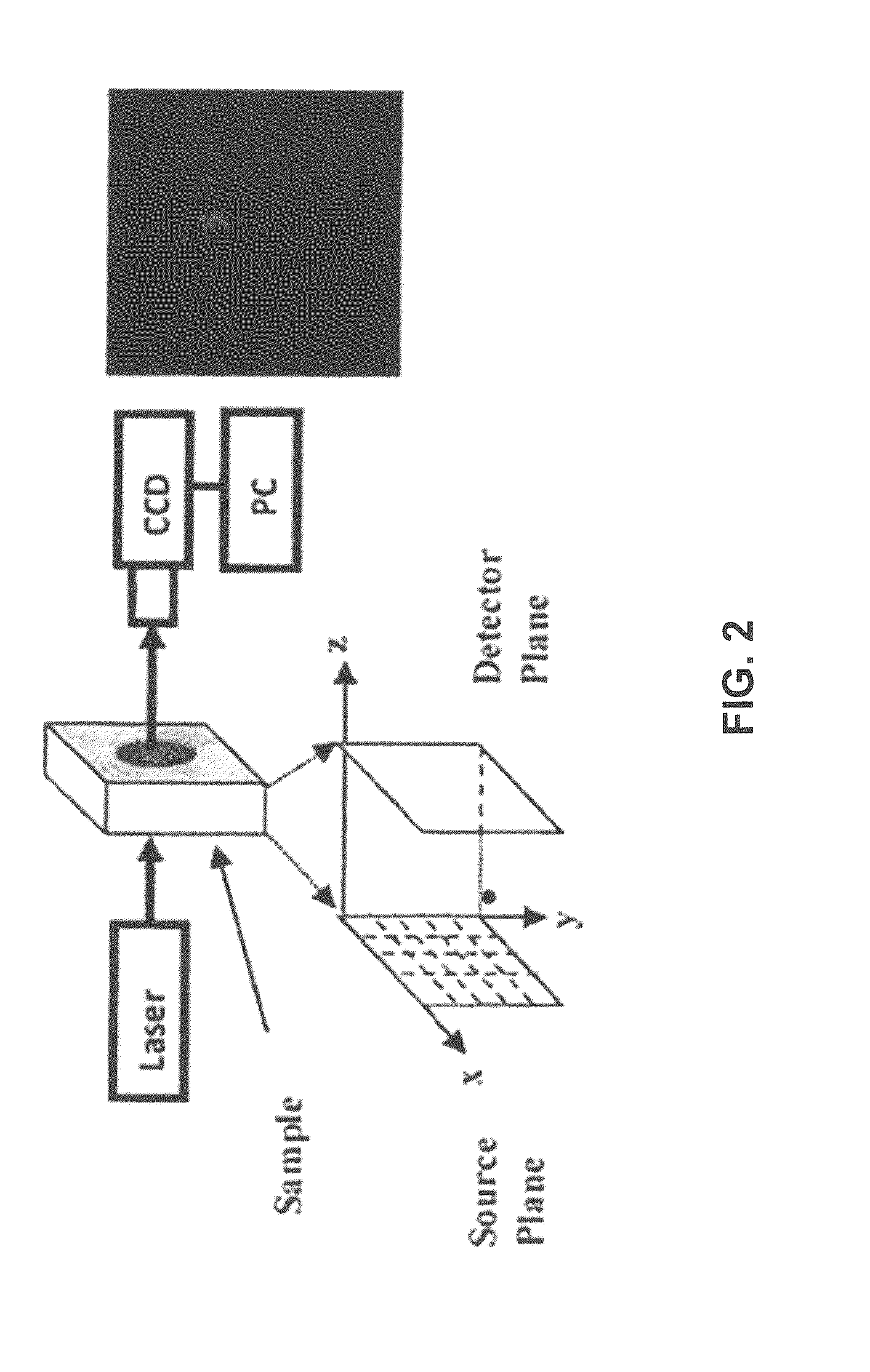
[0065]In the first experiment, the depth (position along z-axis) of an absorptive target was varied to explore how the accuracy of position estimate depended on depth. The target was a glass sphere of diameter 9 mm filled with ink dissolved in Intralipid-20% suspension in water (μs, was adjusted to be the same as that of the background medium, while μa≈0.013 min−1 was about three times higher than that of background medium).

[0066]In the second experiment, the separation between two absorptive targets was varied to test how close those could be and yet be resolved as separate objects. Both the targets were similar to the target in the first experiment.

[0067]In the third experiment, the depth of a scattering target was varied to explore the efficacy of TROT in locating and characterizing a scattering target. The target was a glass sphere of diameter 10 mm filled with Irmalipid-20% suspension in water to provide a transport mean free path of ...

example 3

Resolving Two Absorptive Targets

[0083]In the second experiment using two targets the depth (4 and height (y) were kept same=30 mm, y=26.0 mm), while three different center-to-center separations, Δx of 12.6 mm, 17.6 mm, and 27.6 mm, between them along the x-axis were considered. A cross-sectional pseudo image of the targets when separated by a center-to-center distance of 27 6 mm, generated using the pseudo spectrum is shown in the left pane of FIG. 5(a). FIG. 5(b) shows a similar image for the separation 12.6 mm (separation between nearest edges ˜4 mm). A similar image for the separation 17.6 mm was also obtained (not shown in the figure). The profiles in the x, y and directions through the right target are shown in the right panes of FIG. 5A, FIG. 5B and FIG. 5C. These profiles were used to assess locations of the targets, and the separation between the two targets. In all cases, the targets were determined to be absorptive, because peaks occurred in the pseudo spectrum with the GF...


PUM


Abstract

A time reversal optical tomography (TROT) method for near-infrared (NM) diffuse optical imaging of targets embedded in a highly scattering turbid medium is presented. TROT combines the basic symmetry of time reversal invariance and subspace-based signal processing for retrieval of target location. The efficacy of TROT is tested using simulated data and data obtained from NIR imaging experiments on absorptive, scattering and fluorescent targets embedded in Intralipid-20% suspension in water, as turbid medium, as well as, a realistic cancerous model breast assembled using ex vivo human breast tissues with two embedded tumors. The results demonstrate the potential of TROT for detecting and locating small targets in a turbid medium, such as, breast tumors in early stages of growth.

Description

CROSS-REFERENCE TO RELATED APPLICATIONS[0001]This application claims priority to U.S. provisional patent application No. 61 / 716,762 (filed Oct. 22, 2012), the entirety of which is incorporated herein by reference.BACKGROUND OF THE INVENTION[0002]Optical imaging of targets embedded in a highly scattering turbid medium, such as, a tumor in a breast, is a challenging problem because light is strongly absorbed and scattered by the medium leading to poor signal-to-noise ratio, as well as, loss of phase coherence and polarization. As a consequence distinct, sharp image of the targets may not be formed directly. Various frequency-domain, time-resolved, and steady-state inverse image reconstruction (IIR) approaches are being pursued to form tomographic images using diffusively scattered light measured at the sample boundary. IIR is an ill-posed problem and the development of reliable and fast approaches remains a formidable task. Recent HR algorithms, such as Newton-Raphson-Marquardt algori...

Claims


Application Information

Patent Timeline
IPC IPC(8): A61B5/00
CPCA61B5/0073A61B5/004A61B5/7225A61B5/4312A61B5/4381A61B5/0071
Inventor WU, BINLINCAI, WEIGAYEN, SWAPAN K.
Owner RES FOUND THE CITY UNIV OF NEW YORK
Learn More