Reflective dental apparatus

a technology of dental equipment and reflectors, which is applied in the field of dental tissue retraction apparatuses and systems to promote ease and accuracy in dental procedures, can solve the problems of patient discomfort, procedure time-consuming, and inconvenient use of these systems

Inactive Publication Date: 2014-04-17
GHAVAMZADEH GITI
View PDF15 Cites 2 Cited by
  • Summary
  • Abstract
  • Description
  • Claims
  • Application Information

AI Technical Summary

Benefits of technology

[0017]It is yet another object of the present invention to provide a reflective oral tissue retractor to painlessly and on a larger scale provide retraction of oral tissue from the field of work in the oral cavity in order to provide lateral views of the working area using two opposing mirrors and to allow reflective light to illuminate the work area.
[0018]It is yet another object of the present invention to provide a reflective oral tissue retractor which can be used in all four quadrants of the mo

Problems solved by technology

Although this genre of system and apparatus may be suited for the particular purpose for which it is addressed, the configurations provided by these systems are not suited for the purpose of dental tissue retraction, as hereinafter described.
This stands particularly evident as these apparatuses are predicated on a multi angular view of the workspace however having to adjust the instrument and reposition it to obtain the view causes the procedure to take longer and ultimately leads to patient discomfort.
Two people attempting to maneuver instruments in what can a very small oral cavity causes a more complicated procedure and again ultimately results in patient discomfort and a longer procedure time.
One of the greatest challenges a dental practitioner faces in operating in the oral cavity is space.
The oral tissue of a patient can often obstruct the field and cause the practitioner to again need an assistant to push the tissue away by the use a separate tongue depressor or similar instrument.
No concurrent design has seen fit to combine a true tissue retractor with a mirrored instrument and in fact, many either are not adaptable to such designs or are intended to illustrate the lack of merit in the designs.
Moreover, some concurrent design cl

Method used


Image

  • Reflective dental apparatus
  • Reflective dental apparatus
  • Reflective dental apparatus

Examples


Embodiment Construction

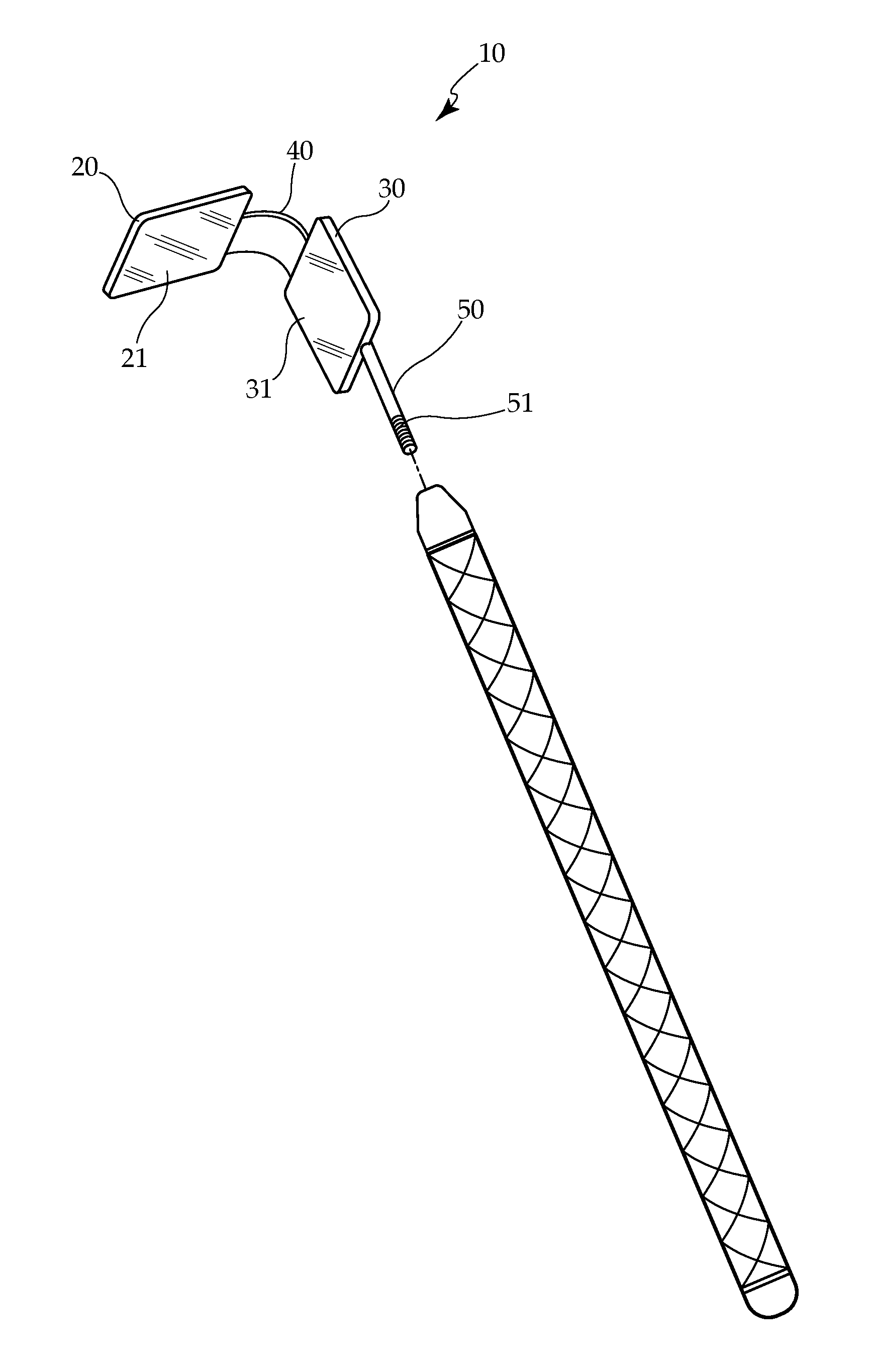
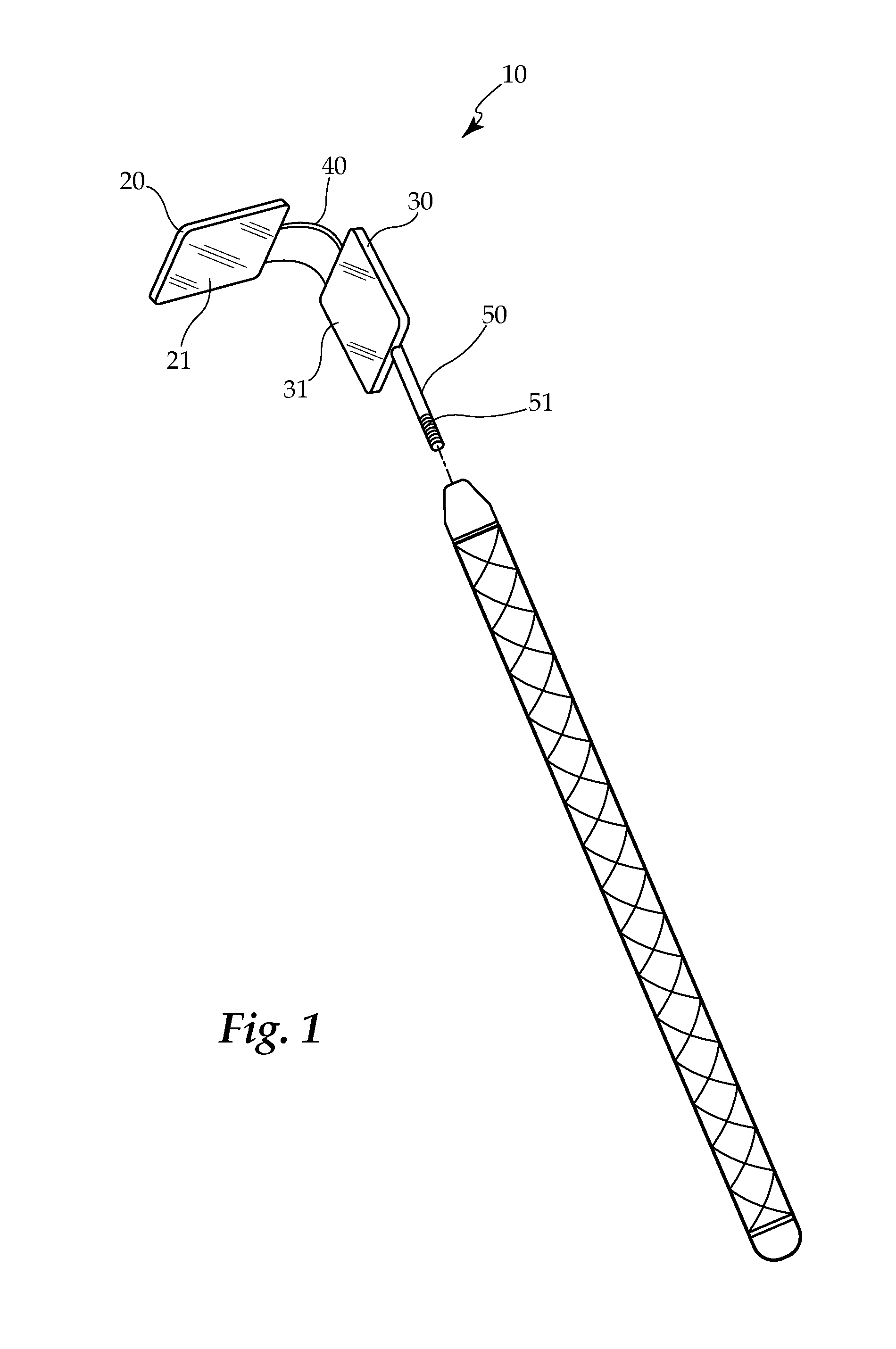
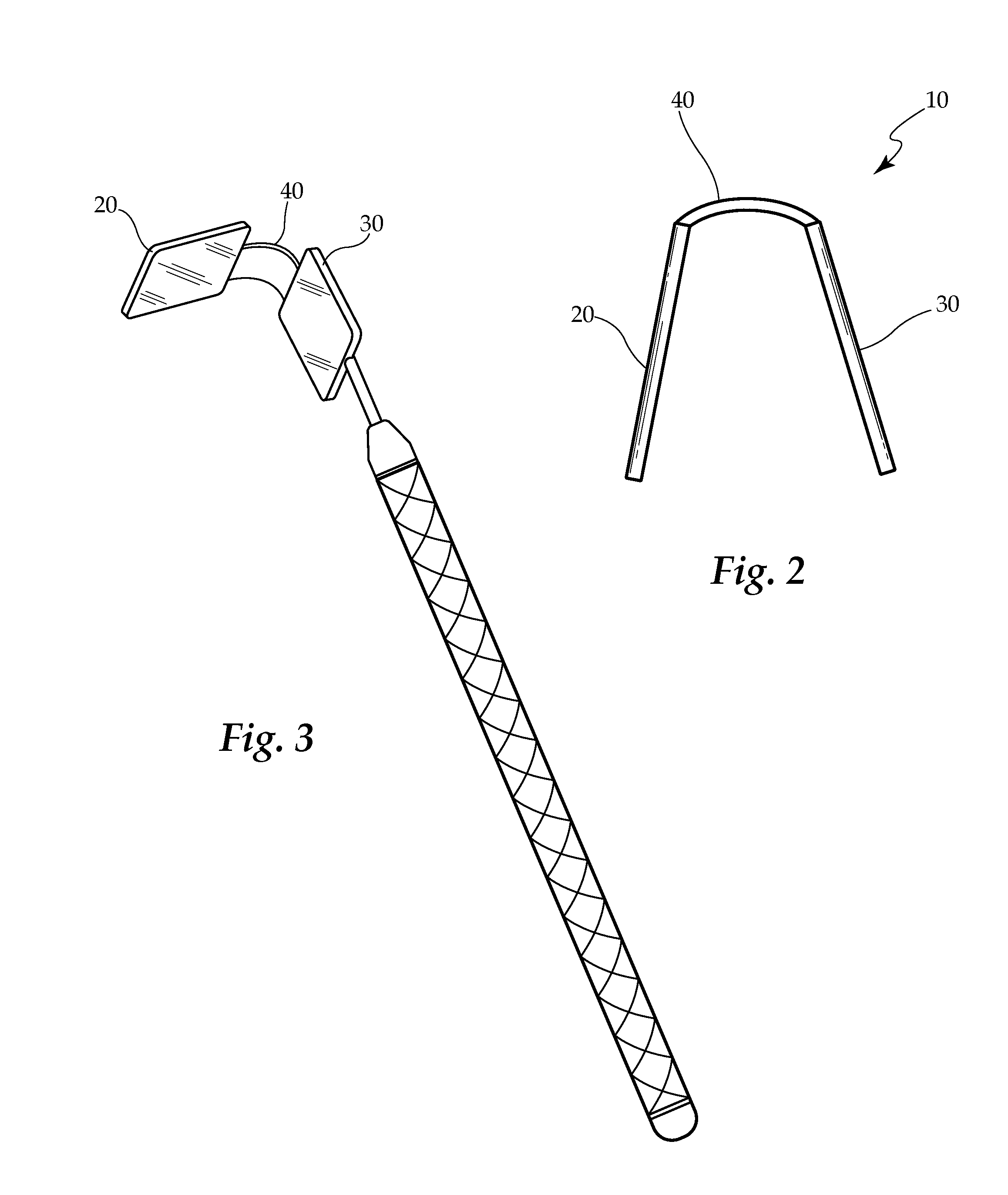
[0033]Turning now descriptively to the drawings, FIG. 1 illustrates the instant AyraDent™ tissue retractor system and apparatus 10 in use with a standard dental handle, wherein the retractor 10 is attached by the arm of the retractor 50 using a threaded end 51. In the instant embodiment, the AyraDent™ tissue retractor system comprises a uni-body attachment head 10 consisting of two substantially rectangular side pieces comprising substantially radial corners 20, that house two reflective surfaces, in one embodiment, mirrors 21, 31 which face each other and are connected by a bridge with a minimal curve 40. In numerous embodiments, mirrors 21, 31 are flat, concave, convex, multi surfaced or any combination thereof.

[0034]In one embodiment, the retractor 10 can come in two forms, the first being a disposable type preferably made of polycarbonate composite or other such material and constructed as a unitary housing the head and containing two front surface mirrors 21, 31. This form can ...


PUM


Abstract

A tissue retractor, for use by dental practitioners, in order to provide clear viewage of a large sector of the oral cavity. The retractor includes a unibody construction in one embodiment, which is intended for attachment to any of the numerous standard dental instrument handles, with two oblong mirrors connected by a bridge, which is static in some embodiments and retractably dynamic in some embodiments. The retractor pulls oral tissue away from the field of work and allows a dental practitioner without the assistance of a Dental assistant to have easy access to the oral workspace and eliminates the need to continually maneuver mirrored tools during procedures.

Description

CROSS REFERENCE TO RELATED APPLICATION[0001]This application claims the benefit of and takes priority from U.S. Application No. 61 / 620,096 filed on Apr. 4, 2012, the contents of which are hereby incorporated by reference.FIELD OF THE INVENTION[0002]This invention relates to apparatuses and systems to promote ease and accuracy in dental procedures. More particularly, the instant invention relates to apparatuses and systems pertaining to dental tissue retraction, and more specifically to retractor attachments that allows the dental practitioner to have a clear oral workspace and allowing ease of placement and lack of a need to maneuver further oral instruments.BACKGROUND OF THE INVENTION[0003]Dental instruments featuring mirrors or in combination, have long been used in the dental field to assist practitioners with viewing the teeth and gums from the various angles present in the oral cavity. These mirrors have historically been circular in shape and feature specialized handles for ma...

Claims


Application Information

Patent Timeline
IPC IPC(8): A61C3/00A61B1/32
CPCA61B1/0008A61B1/247
Inventor GHAVAMZADEH, GITI
Owner GHAVAMZADEH GITI
Why Eureka
Try Eureka