
Fuel cell with improved thermal management

a fuel cell and thermal management technology, applied in the direction of fuel cells, fuel cell auxilaries, electrochemical generators, etc., can solve the problems of increasing head loss, reducing the temperature of the second stack, and damage to the material making up the fuel cell, so as to avoid the effect of heat imbalance between the stacks

Active Publication Date: 2014-04-17
COMMISSARIAT A LENERGIE ATOMIQUE ET AUX ENERGIES ALTERNATIVES
View PDF3 Cites 2 Cited by
  • Summary
  • Abstract
  • Description
  • Claims
  • Application Information

AI Technical Summary

Benefits of technology

The present invention provides a fuel cell with multiple stacks that have a balanced temperature. The fuel cell includes a heat management system with a coolant flow system and valves that control the flow of coolant. The valves ensure that there is a low coolant flow resistance and an equal heat loss between the stacks. This system helps to avoid heat imbalances and reduces the space required for the fuel cell.

Problems solved by technology

Indeed, if the operating temperature is too low, the best operating efficiency of the fuel cell cannot be achieved, and if the fuel cell undergoes too high a temperature rise, the materials making up the fuel cell can be damaged.
But the head loss increases because of the passage through the heat exchanger.
However, since the total flow rate provided by the pump remains identical, the flow rate in the second coolant increases, which causes an increase in the heat exchange in the second stack, and thus a decrease in the temperature of the second stack.
Then, there occurs an amplification of the heat imbalance between both stacks, which can compromise the integrity of the electrochemical membranes of the hottest stack.

Method used


Image

  • Fuel cell with improved thermal management
  • Fuel cell with improved thermal management
  • Fuel cell with improved thermal management

Examples


Embodiment Construction

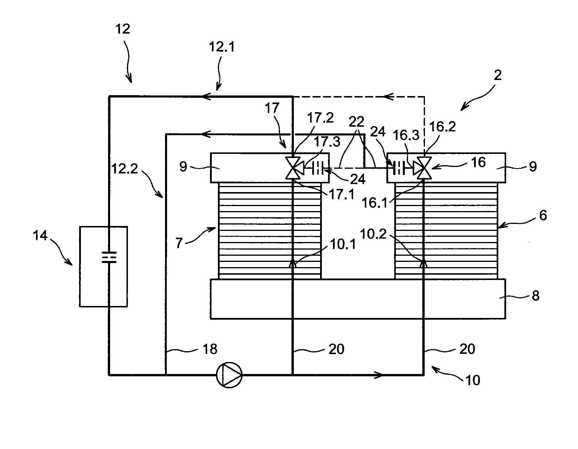
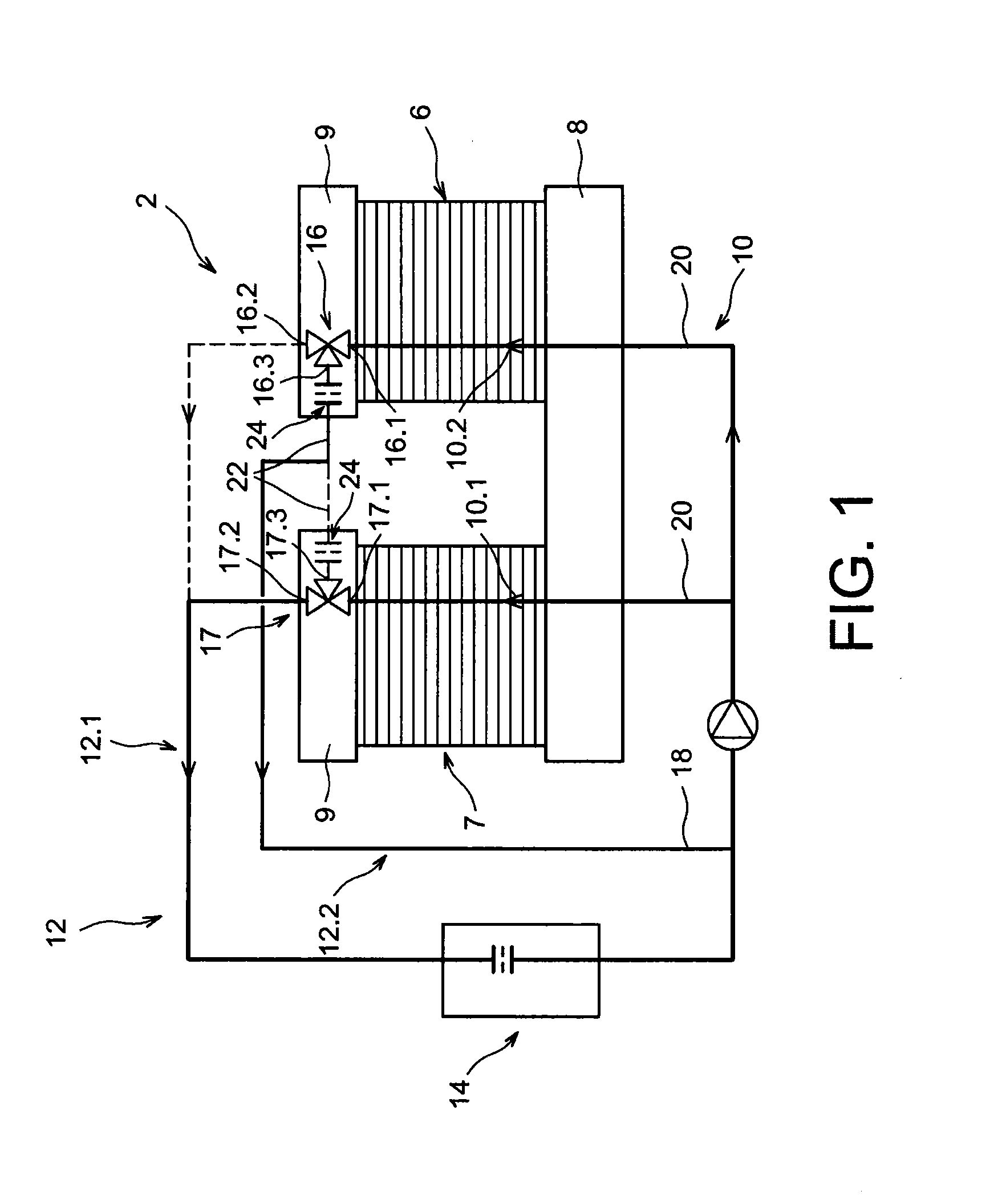
[0034]In FIG. 1, there can be seen a schematic representation of a fuel cell 2 equipped with a heat control system 4.

[0035]The fuel cell 2 comprises two stacks 6, 7 of electrochemical cells comprised of bipolar plates and ion exchange membranes alternately provided, and downstream 8 and upstream 9 end plates on either side of the stacks.

[0036]The end plates 8, 9 exert a compressive strain onto the stacks 6, 7 to ensure an electrical conduction evenly distributed throughout the surface of the elements making up the cells. In the example represented, the cell comprises an upstream end plate common to both stacks, but they could be separated. The downstream end plates could also be replaced by a common plate.

[0037]Besides, the supply of cells with reactive fluid, for example hydrogen on the one hand and oxygen on the other hand, is made through either or both end plates 8, 9. The end plate(s) comprise(s) supply and discharge ports connected both to a circuit within the stacks, and to a...


PUM

PropertyMeasurementUnit
temperatureaaaaaaaaaa

Abstract

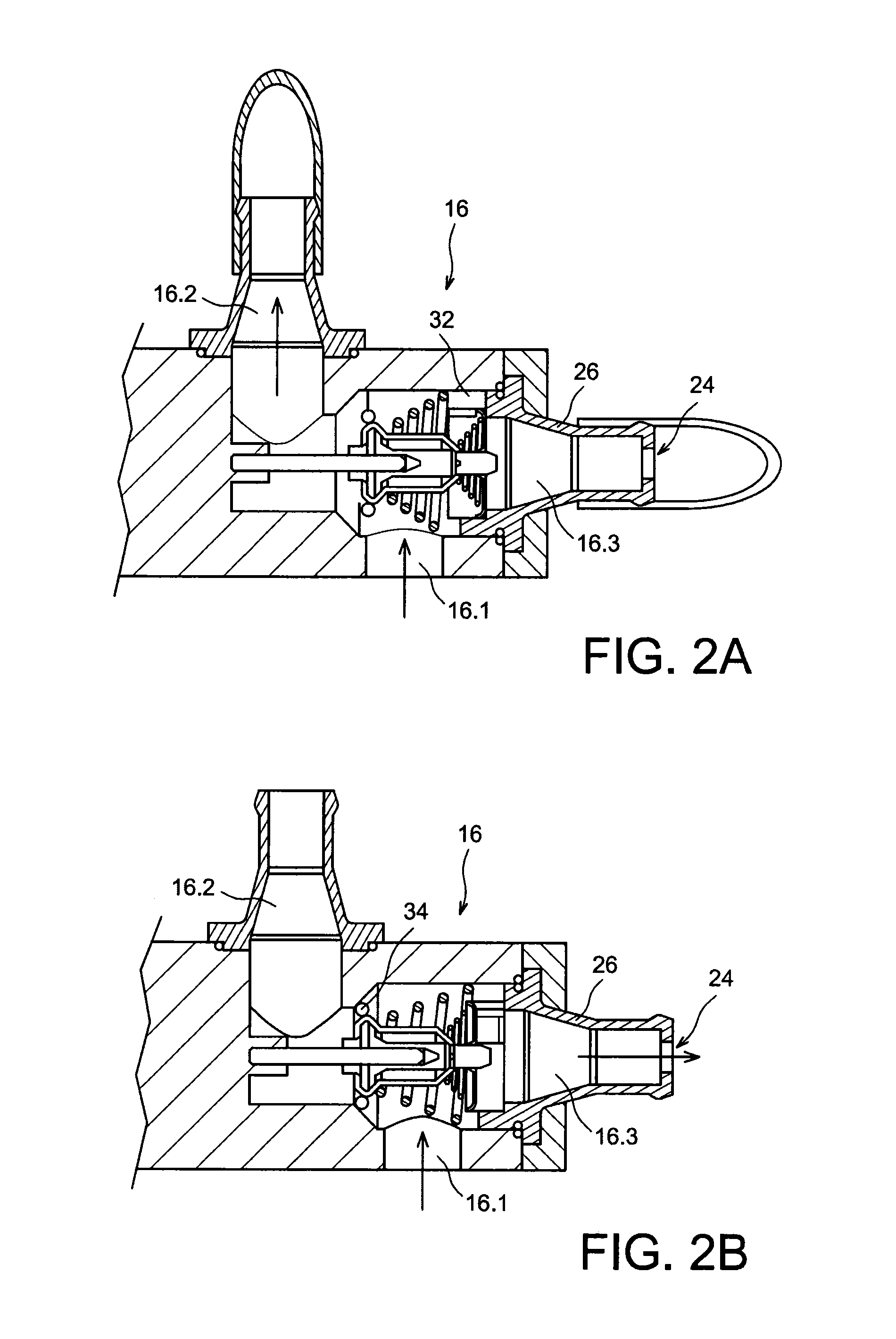
A fuel cell including at least two stacks of electrochemical cells, a heat management system including a circuit for flowing a coolant into each of the stacks fed in parallel, and an outside circuit for flowing the coolant outside the stacks. The outside circuit includes a first subcircuit including a heat exchanger and a second subcircuit directly connected to an inlet of the inside circuit, and controlling valves for controlling flow of the coolant toward either or both subcircuits as a function of temperature of the coolant at an output of each of the stacks. The second outside subcircuit includes a mechanism increasing its head loss such that it is close or equal to that of the first outside subcircuit.

Description

TECHNICAL FIELD AND PRIOR ART[0001]The present invention relates to a fuel cell with improved heat management.[0002]A fuel cell, to deliver electricity, is supplied with fuel gas, for example hydrogen in the case of a cell of the proton exchange membrane fuel cell (PEMFC) type, and in oxidizing gas, for example air or oxygen.[0003]The operation of the fuel cell also results in generating heat energy.[0004]A fuel cell comprises a stack of electrochemical cells, each cell comprising an anode and a cathode. The cells are kept compressed against each other by end plates connected by tie rods.[0005]A circuit is provided to supply reactive gases in cells. On the other hand, the electrochemical efficiency of the fuel cell is dependent on the temperature within the cell because of the very nature of the materials used. Consequently, this temperature should be monitored in order not to exceed 80° C. and to obtain the highest possible efficiency. Indeed, if the operating temperature is too lo...

Claims


Application Information

Patent Timeline
Patent Type & Authority Applications(United States)
IPC IPC(8): H01M8/04
CPCH01M8/04074H01M8/04029H01M8/04067H01M8/04768H01M8/248H01M8/249H01M2008/1095Y02E60/50H01M8/0267H01M8/2465
Inventor DROUHAULT, DELPHINENIVELON, PIERRE
Owner COMMISSARIAT A LENERGIE ATOMIQUE ET AUX ENERGIES ALTERNATIVES
Learn More