
Isolated interleaved DC converter

a dc converter and interleave technology, applied in the direction of electric variable regulation, process and machine control, instruments, etc., can solve the problems of low output voltage, electric magnetic interruption (emi), and the switching loss of the switching element increases accordingly, and achieves the effect of soft switching effect of the switching element and high voltage conversion

Inactive Publication Date: 2014-04-17
NATIONAL TSING HUA UNIVERSITY
View PDF6 Cites 17 Cited by
  • Summary
  • Abstract
  • Description
  • Claims
  • Application Information

AI Technical Summary

Benefits of technology

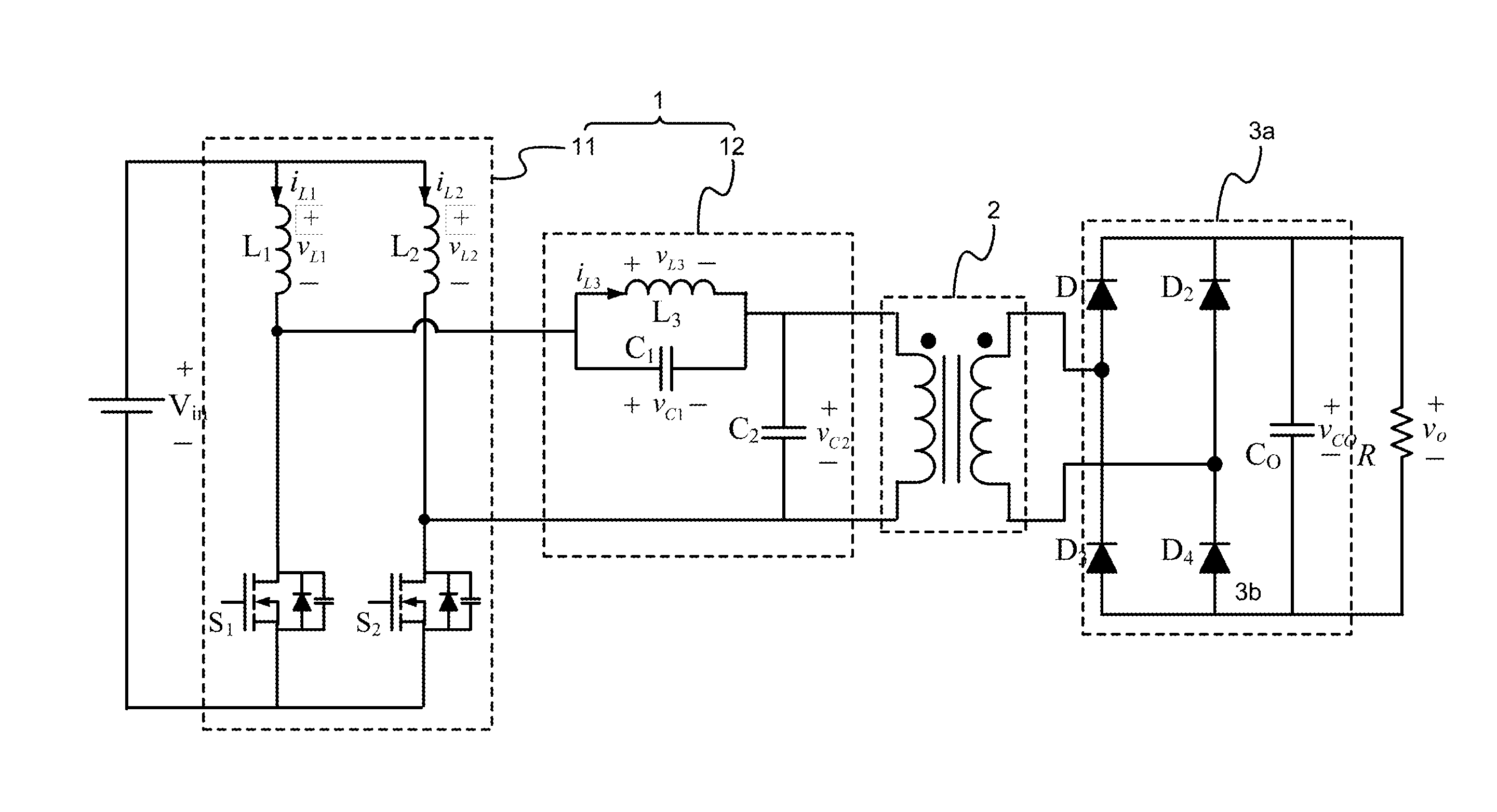
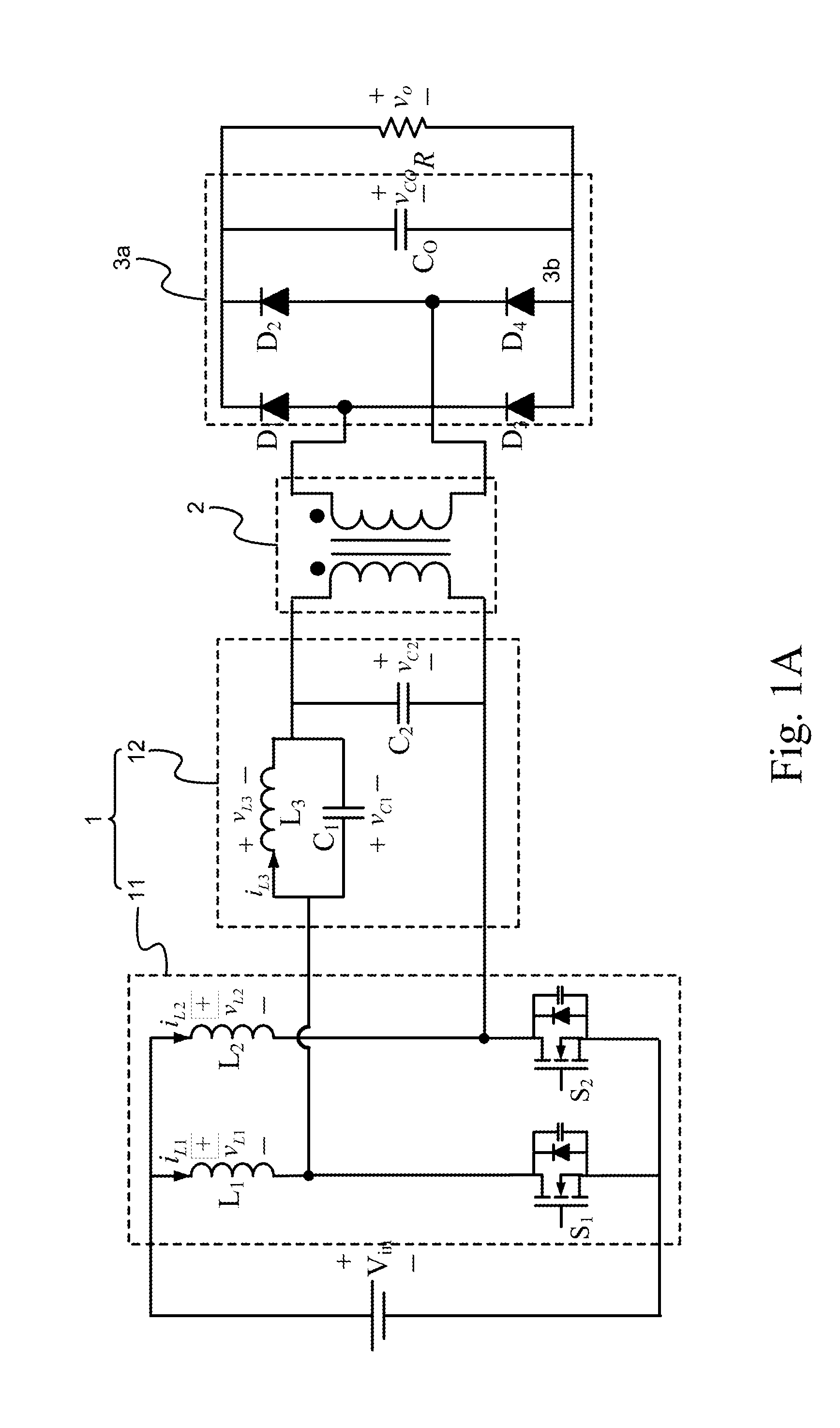
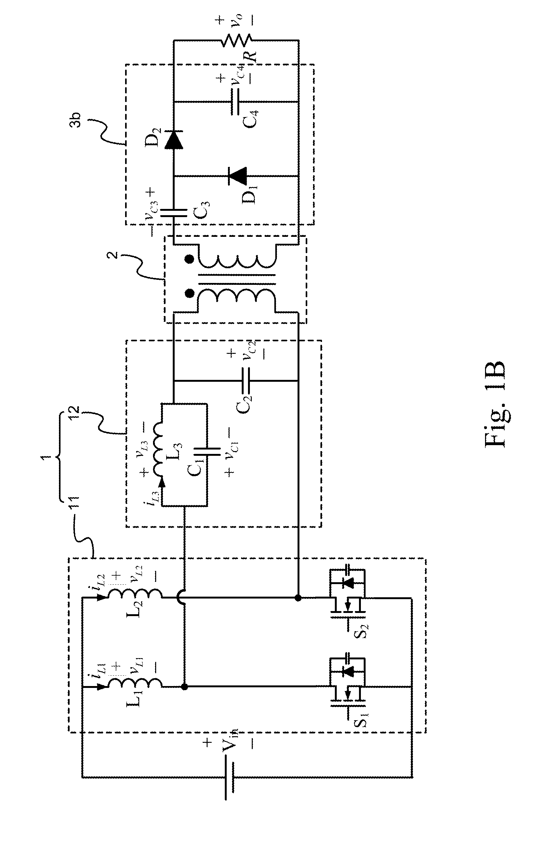
The invention provides a DC converter with high voltage conversion that integrates soft switching technology. It combines a transformer and a voltage type auto charge pump circuit with a dual-phase interleaved boost circuit at the primary side of the transformer. The design of circuit parameters and the action of the LC resonant circuit grant the circuit with characteristics of variable circuit architecture and achieve the soft switching effect for switching elements. Additionally, it integrates a double-voltage rectifier circuit at the secondary side of the transformer to further enhance the output voltage, and reduces electric magnetic interruption (EMI) and the switching losses while increasing circuit conversion efficiency. Furthermore, it has low output voltage ripple, avoids using large-capacititance electrolytic capacitors, extends the service life of the transformer, and achieves high power density, high voltage conversion ratio, low costs, low EMI, low output voltage ripple, long service life, and high conversion efficiency.

Problems solved by technology

However, the photovoltaic systems and the fuel cells have low output voltage, and therefore rely on high step-up ratio power converters to increase the output voltage for back-end applications.
However, while enhancing the switching frequency of the conversion circuit, the switching loss of the switching elements increases accordingly.
Problems such as electric magnetic interruption (EMI) occur as well.
Therefore, the conventional converter circuit cannot meet the need for users in actual use any more.

Method used


Image

  • Isolated interleaved DC converter
  • Isolated interleaved DC converter
  • Isolated interleaved DC converter

Examples


Embodiment Construction

[0034]The aforementioned illustrations and following detailed descriptions are exemplary for the purpose of further explaining the scope of the present invention. Other objectives and advantages related to the present invention will be illustrated in the subsequent descriptions and appended tables.

[0035]FIG. 1A through FIG. 1G are respectively a schematic diagram of a full-bridge rectifier circuit at a secondary side of a transformer of an isolated interleaved DC converter circuit, a schematic diagram of a double-voltage rectifier circuit at a secondary side of a transformer of an isolated interleaved DC converter circuit, a schematic diagram of a rectifier circuit at a secondary side of a transformer of an isolated interleaved DC converter circuit, a schematic diagram of a triple-voltage rectifier circuit at a secondary side of a transformer of an isolated interleaved DC converter circuit, a schematic diagram of a four times-voltage rectifier circuit at a secondary side of a transf...


PUM


Abstract

An isolated interleaved DC converter has a main circuit architecture integrating a transformer, a dual-phase interleaved step-up circuit, a voltage type auto charge pump circuit with a double-voltage rectifier circuit. The circuit of the invention integrates with the transformer, and combines the dual-phase interleaved boost circuit and the voltage type auto charge pump circuit at a primary side of the transformer to reduce the input current ripple. At a secondary side of the transformer, the circuit of the invention further combines the double-voltage rectifier circuit. The active switching elements can be further integrated in the dual-phase interleaved boost circuit to realize the soft switching technology while reducing EMI and the switching loss and increasing the circuit conversion efficiency.

Description

BACKGROUND OF THE INVENTION[0001]1. Field of the Invention[0002]The present invention relates to an isolated interleaved DC converter, and particularly to a DC converter which has an integrated soft switching technology with high voltage conversion. More particularly, the present invention relates to a converter circuit which integrates a transformer, combines a voltage type auto charge pump circuit with a dual-phase interleaved boost circuit at a primary side of the transformer, and grants the circuit with characteristics of variable circuit architecture and soft switching effect for switching elements by the design of circuit parameters and the action of the LC resonant circuit.[0003]2. Description of Related Art[0004]A double-voltage circuit is mainly constituted by a diode and a capacitor. Its action is to output a rectified voltage peak value after magnitude, and it is often used to applications which need high voltage and low current. FIG. 7 shows that a dual-phase interleaved...

Claims


Application Information

Patent Timeline
IPC IPC(8): H02M3/335
CPCH02M3/335H02M3/07Y02B70/10H02M1/0058H02M3/33571H02M3/01
Inventor PAN, CHING-TSAICHEN, PO-YENCHENG, MING-CHIEHCHENG, CHING-HSIANG
Owner NATIONAL TSING HUA UNIVERSITY
Learn More