
Method of tube-necking spinning and apparatus therefor

a technology of tube-necking and spinning rods, which is applied in the field of spinning metal processing methods and apparatus therefor, can solve the problems of limited feeding rate, limited rotating speed, and several limitations of known fabrication methods for srf cavities, and achieves the reduction of the diameter ratio of the former, shortening the roller path, and increasing the feeding rate

Inactive Publication Date: 2014-04-17
BAILEY TOOL & MFG
View PDF4 Cites 6 Cited by
  • Summary
  • Abstract
  • Description
  • Claims
  • Application Information

AI Technical Summary

Benefits of technology

The present invention is a new method and apparatus for spinning processing of metal tubes and similar work pieces, which solves problems and difficulties associated with conventional spinning methods. The invention uses a two-step spinning process and specially profiled rollers, which increases feeding rate, shortens roller paths, and accurately controls spun shapes, resulting in high efficiency and accuracy in spin forming metal tubes. The invention is particularly well-suited for spinning seamless multi-cell SRF cavities for particle accelerators.

Problems solved by technology

Known fabrication methods for SRF cavities have several limitations, especially for mass production of seamless multi-cell SRF cavities.
Tube-necking spinning remains the main challenge for mass production of seamless multi-cell SRF cavities.
For a certain material, the rotating speed is limited, and feeding rate is also limited for the given roller shape.
Because of the limitation of high rotating dynamics in the spinning, it is impossible to greatly increase the rotating speed.
The present inventor has found that it is very difficult to reduce the processing time in the conventional spinning processing methods.
The main drawbacks of conventional spinning include: very long processing time so the efficiency is very low.
First, the feeding in each spinning pass is small when using very simple roller shapes in which the maximum feeding is limited.
On the other side, the total length of roll path is too long, especially in cases like SRF cavities in which the diameter reduction ratio is very high.
Secondly, a mandrel is needed, and only the very complicated collapsible mandrel like disclosed in U.S. Pat. No. 5,500,995 can be used for multi-cell tube-necking shapes, such as SRF cavities.
Thirdly, it is very difficult to obtain ideal spun profiles as the simple roller shape, especially if a mandrel is not used in the spinning.
For SRF cavities, as the interference zone exists and the mandrel difficulty issue exists when starting from a tube blank, it is too difficult and too expensive to use a mandrel in spinning full multi-cell shapes.
For a single cell cavity the former method worked, but necking of the multi-cells was less successful.
For a long tube it was difficult to achieve the uniform wall thickness at the necking area.
It needs a special device that may cause vibration problems.
They do not have the ability to produce the full cell shapes of multi-cell SRF cavities.

Method used


Image

  • Method of tube-necking spinning and apparatus therefor
  • Method of tube-necking spinning and apparatus therefor
  • Method of tube-necking spinning and apparatus therefor

Examples


example 1

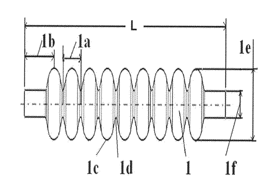
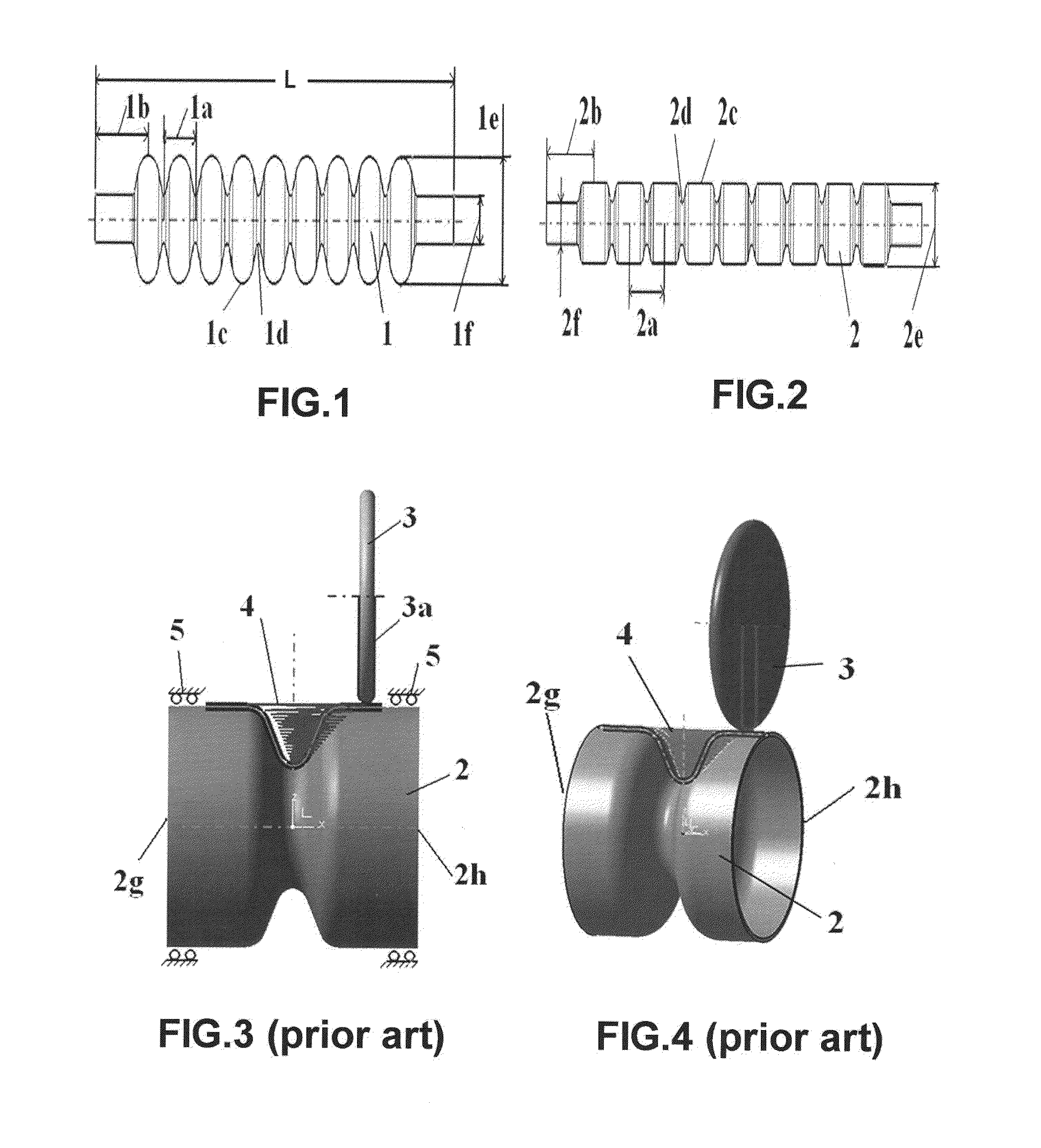
[0046]FIG. 2 is a schematic view showing an example of a nine-cell SRF cavity according to an embodiment of the present invention. In this example, the starting tube diameter 2e is an intermediate diameter between equator 1e and iris 1f, and the tube-necking spinning is as a preform process, followed by hydroforming to form to final part shape of FIG. 1.

example 2

[0047]FIG. 1 is the final part shape of FIG. 2, and FIG. 1 is also another example of a nine-cell SRF cavity according to an embodiment of the present invention. In this example, the starting tube diameter roughly equals equator diameter 1e, and the tube-necking spinning is the main forming process, directly spinning to the part shape of FIG. 1. Following this, only calibration operation by hydroforming or other forming is required to achieve accurate final part shape.

example 3

[0048]For mass production, the present invention can also be used on separate spinning equipment to further increase production: applying the primary forming rollers 6 and the first step to one machine, and applying the secondary forming rollers 8 and the second step to another machine. Similarly, the two-step method of present invention may be applied to each of multiple machines, or some for first step and others for second step.


PUM

PropertyMeasurementUnit
Lengthaaaaaaaaaa
Diameteraaaaaaaaaa
Shapeaaaaaaaaaa

Abstract

A two-step method and apparatus therefor provide cost-effective processing of tube-necking spinning for Superconducting Radio Frequency (SRF) cavities. A metal tube as a work piece may be rotated round its longitudinal axis; the target shape is obtained gradually in two steps by driving specially profiled rollers along roller paths moving in radial and axial directions. Alternatively, the rollers may rotate around a stationary work piece. To spin one cell, in the first step, a primary forming roller moves along a roller path to form a partial necking shape; then, in a second step, a secondary forming roller moves along a roller path to continue necking processing; and finally, the full cell is formed. To spin multi-cells, this two-step method is repeated for each cell. No additional equipment is required as rollers are mounted the same as in conventional spinning The cost is reduced by applying a rapid feeding rate, greatly shortening the length of the roller path, accurately controlling the spun profile and eliminating a complicated mandrel.

Description

BACKGROUND OF INVENTION[0001]1. Field of the Invention[0002]The invention relates generally to a spinning metal processing method and apparatus therefor, and articles manufactured according to the method. More specifically, the invention comprises a two-step tube-necking spinning method in which a series of primary forming rollers used in a first step is followed by a series of secondary or finishing forming rollers used in a second step, the rollers having specially profiled section shapes, and product produced thereby.[0003]2. Description of Related Art[0004]Spinning is a metalworking process by which a disc or tube of metal is rotated at high speed and formed into an axially symmetric part. It typically involves the forming of axisymmetric components over a rotating mandrel using rigid tools or rollers. Tube-necking spinning is one type of spinning method in which a metal tube is processed to form a section of reduced diameter.[0005]SRF (Superconducting Radio Frequency) cavities ...

Claims


Application Information

Patent Timeline
IPC IPC(8): B21D22/14
CPCB21D15/06B21D22/18
Inventor WANG, YUYUAN
Owner BAILEY TOOL & MFG
Learn More