
Serializer-deserializer clock and data recovery gain adjustment

a serializer and deserializer technology, applied in the direction of electrical equipment, pulse automatic control, etc., can solve the problems of large variations in data lock time and jitter tolerance, and designers often encounter difficulties when attempting to limit the calibration of vco

Active Publication Date: 2014-04-10
AVAGO TECH INT SALES PTE LTD
View PDF1 Cites 23 Cited by
  • Summary
  • Abstract
  • Description
  • Claims
  • Application Information

AI Technical Summary

Benefits of technology

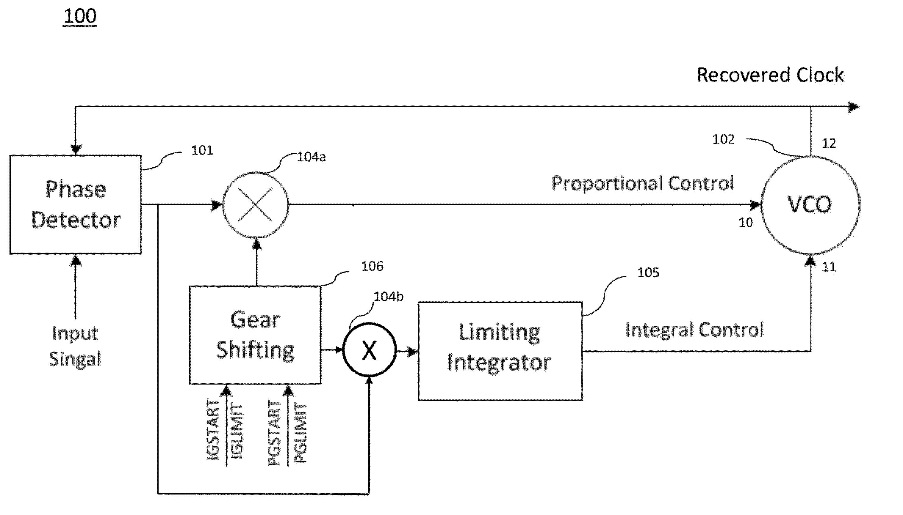
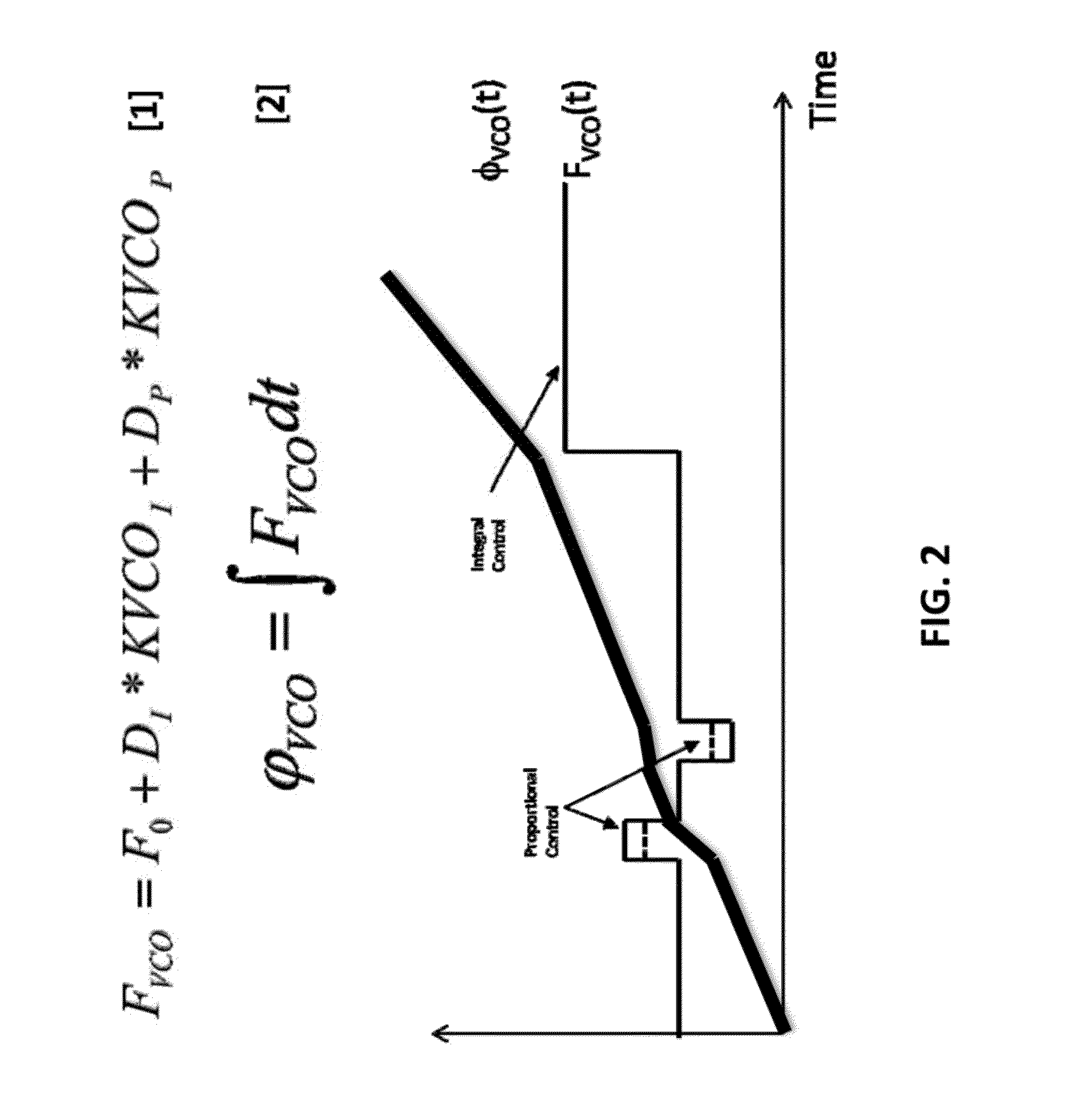
The patent describes an adjustment system for a clock and data recovery circuit that uses a voltage-controlled oscillator (VCO). The system detects a phase difference between input and feedback signals and combines them with gear shifting control signals to create a control signal for the VCO. The output of the VCO is then sent back to the phase detector as feedback. The system includes a frequency calibration module that performs coarse and fine calibrations to the calibrated reference frequency of the VCO. The gain of the circuit is adjusted by adjusting gear shifting up or down using the fine calibration values stored in a look-up table. The technical effect is an improved accuracy and accuracy of the adjustment system that ensures the proper functioning of the clock and data recovery circuit.

Problems solved by technology

The existing voltage-controlled oscillator (VCO)-based CDR in a SerDes device often exhibits large variations in data lock time and jitter tolerance due to a relatively-high, non-linearity of the VCO.
A designer often encounters difficulties when attempting to limit calibration of the VCO to an acceptable linear region, especially over large process, supply voltage and temperature (PVT) variations.

Method used


Image

  • Serializer-deserializer clock and data recovery gain adjustment
  • Serializer-deserializer clock and data recovery gain adjustment
  • Serializer-deserializer clock and data recovery gain adjustment

Examples


embodiment 400

[0049]In the embodiment 400, at step 403, the proportional and integral control signals might be set to midrange signals for VCO 302. At step 404, an output frequency of VCO 302 might be divided to a calibration reference frequency by a programmable divider (not shown). The divider might be configured to divide the frequency of the output signal generated from VCO 302 with a given dividing ratio. One of the divided signals of the output frequency of VCO 302 might be sent back to phase detector 301 as the feedback signal. Another one of the divided signals might be sent to frequency calibration module 303 as the calibration reference frequency, which might be compared to the reference clock frequency form a reference clock over a period of time. At step 405, frequency calibration module 303 might perform a coarse calibration of VCO 302 with the calibration reference frequency and a reference clock frequency from a reference clock. The coarse calibration might be done by changing supp...

embodiment 500

[0053]As shown, embodiment 500 includes phase detector 501, RXVCO 502, frequency calibration module 503, control multipliers 504a and 504b, limiting integrator 505, gear shifting control module 506, multiplexer 507, look-up table (LUT) 508, calculation circuit 509, channel 510, receiver front end (RXFE) 511, adder or summing node 512, slicers 513, deserializer 514, decision feedback equalization (DFE) 515, and receiver equalization (RXEQ) adaption 516. Generally, phase detector 501, RXVCO 502, frequency calibration module 503, limiting integrator 505, gear shifting control module 506, multiplexer 507, look-up table (LUT) 508, and calculation circuit 509 are identical in constitution and operation to phase detector 301, VCO 302, frequency calibration module 303, limiting integrator 305, gear shifting control module 306, and multiplexer 307 illustrated in FIG. 5. Control multipliers 504a, 504b are identical in constitution and operation to control multipliers 304a and 304b illustrated...


PUM


Abstract

In described embodiments, a VCO based CDR for a SerDes device includes a phase detector, a VCO responsive to a first control signal and a second control signal and generating an output signal, a frequency calibration module configured to calibrate the frequency of the output signal by performing a coarse calibration and a subsequent fine calibration, a gear shifting control module controlling a gain, change of the first and second control signals in time, and a look-up table created by fine calibration values generated from the frequency calibration module, wherein the programmed variable gain of the gear shifting control module is calculated by a calculation circuit employing the fine calibration values stored in the look-up table, the calculation of the calculation circuit adjusts gear shifting down, and adjusts a gear shifting gain, and adjusting an overall CDR gain over a VCO control curve.

Description

BACKGROUNDDescription of the Related Art[0001]In many applications, including digital communications, clock and data recovery (CDR) systems are employed to recover correct timing (frequency and phase) of an input data stream, which timing is then employed to sample the input data stream to recover the user data for decoding. A serializer-deserializer (SerDes) device is commonly used in high speed communications to convert data between serial and parallel interfaces in each transmit / receive direction.[0002]SerDes devices often employ an encoding scheme that supports DC-balance, provides framing, and guarantees signal transitions. Guaranteed transitions allow a receiver to extract the embedded clock signal (clock data recovery, or CDR), while control codes allow framing, typically on the start of a date packet. This encoding scheme also improves error detection with running disparity, providing separation of data bits from control bits, and permits derivation, of byte and word synchro...

Claims


Application Information

Patent Timeline
IPC IPC(8): H03L7/08
CPCH03L7/0807H03L7/087H03L7/1075H03L7/146H03L2207/06
Inventor SINDALOVSKY, VLADIMIRANIDJAR, JOSEPHSMITH, LANE A.HARDY, BRETT DAVID
Owner AVAGO TECH INT SALES PTE LTD
Learn More