
Tool Holding Device

a tool and tool technology, applied in the field of tools, can solve the problems of not being able to effectively decouple the swinging motion of the attached tool from the user, not having a known prior art or invention that can safely, and not being able to withstand the constant abuse of construction, etc., to achieve the effect of safely climbing ladders, convenient removal, and safe and convenient mounting

Inactive Publication Date: 2014-04-10
WALSH SEAN MICHAEL
View PDF0 Cites 44 Cited by
  • Summary
  • Abstract
  • Description
  • Claims
  • Application Information

AI Technical Summary

Benefits of technology

The present invention is a tool holding device that can safely attach to a tool handle and allow users to conveniently hang the tool from various sites such as rafters, belts, ladder rungs, pant pockets, and tool bags, without the risk of accidental detachment. The device also allows for the interchangeable attachment of various tool safety and convenience accessories to tools.

Problems solved by technology

For the most part these tool holders only work with a small subset of tools that are commonly used because of limited strength and limited range of adjustment on the portion that actually holds the tool.
In general these tool holding devices are constructed out of plastic, aluminum, light weight metals and elastic, and are not capable of enduring the constant abuse that takes place in construction.
There is no known prior art or invention that can safely and securely hold power tools that weigh upwards of twenty pounds to a tool user so they may carry their tool up a ladder and work in dangerous situations using both hands.
Other devices in the prior art do not effectively decouple the swinging motion of attached tools from the user during user movement.
Other tool holder devices in the prior art do not hold the attached tool out and away from the user thus causing frequent collisions between the tool and user as the user moves about on a job site.
No known tool holder device in the prior art can operate to removeably secure and lock the tool to the user or alternatively securely fastening and locking to a common building material such as a rafter or joist without interruption or adjustments of the device.
A tool could be held by this hook, however there is nothing provided to keep the tool from becoming dislodged from the surface it is hung on and injuring a person working below.
Since the hook relies on gravity alone to hold it to the user and has no other securing structure, it also does not prevent tools from being dislodged and falling and breaking on the ground.
This invention also does not provide the user the ability to interchangeably use different attachments such as a lanyard, or a hook or a flashlight for safety and convenience.
Another shortcoming of the Warner invention is the inability to safely and securely attach a device to a tool handle that can support the tools weight without it being cumbersome and awkward to work with.
It also will not allow the user to be able to secure it to any tool common to the construction industry.
When used on a very small tool handle, there would remain a large amount of excess strap that becomes cumbersome to work with.
When secured on a very large handle the strap could be too short and not able to adequately stay attached to the handle.
This prior art device suffers from the same shortcomings of the Warner invention in that it does not permit pivoting of the attached tool to accommodate mass imbalances and allow the tool to pivot to a position of equilibrium.
Once again the present art does not meet the need to safely and securely protect tools and workers from damaging falls.
Also the present art does not meet the need to be able to securely hold tools to objects that are common to the construction industry.
Piatt also does not hold the attached tool out and away from the user which would result in frequent collisions between the user and the attached tool.
Durham does not hold the attached tool out and away from the user which would result in frequent collisions between the user and the attached tool.
The uses of the above invention are limited to specifically shaped tools that do not exceed certain weights, and the design does not allow the tool to attach to anything besides it's socket-shaped receiver.
Users also complain that the bungee interferes with their ability to comfortably grip the tool handle.
Nothing disclosed in Axelman would allow the tool to be securely attached to anything besides the cone shaped receptacle.
These inventions are also limited in function and will not allow for the tool to be secured to anything besides the receiving member.
Nothing in Albert discloses a universal mechanical fastening device and instead only shows a clip that would need to be custom made for every variation of common tools which would be very costly to manufacture.
Nothing disclosed in Axelman would allow the tool to be securely attached to anything besides the provided belt mount.
Once again, Alberts invention like the others, only depends on gravity to hold the tool to the user and does not provide means to lock the tool within a holder to prevent accidental dislodgments of the tool.
Albert also does not provide means for a tool to pivot thus decoupling the tools swinging motions.
Also the prior art does not meet the need for a tool holder that would allow various tools to be secured to common items in the construction industry, such as, rafters, joists, plywood, shingles, electrical wires, water pipes; as well as allowing the tool to be secured to the tool user, ladder rungs, and ladder tops.
The prior art also does not fulfill the need for a tool holder that can be attached to nearly any hand held tool, no matter the weight, shape, or size, and also allow the tool to be secured to whatever is handy.
Still further, the tool accessory mounting device disclosed within provides unmatched securing and safety options by allowing tool users the ability to both lock their tools within a belt mounted holder while at the same time having a lanyard attached to the tool to prevent the tool from being dropped when it is not locked into the holder.

Method used


Image

  • Tool Holding Device
  • Tool Holding Device
  • Tool Holding Device

Examples


Embodiment Construction

FIGS. 1-13—Preferred Embodiments

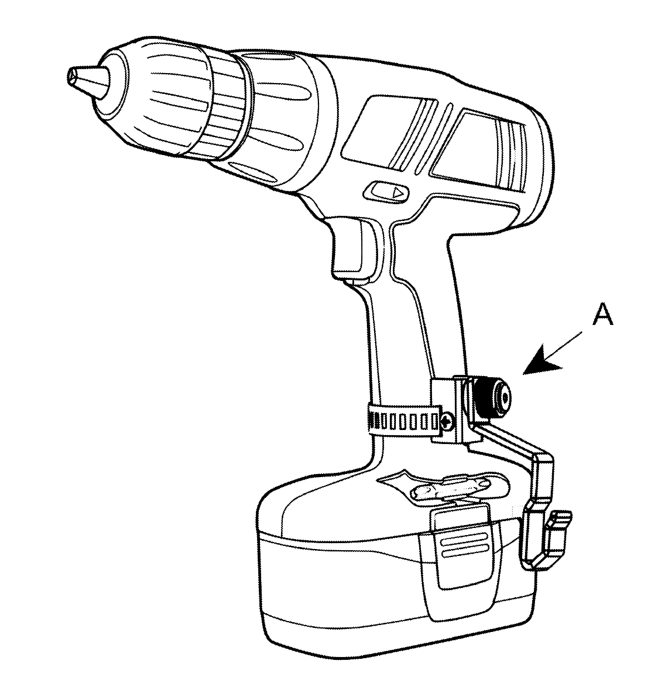
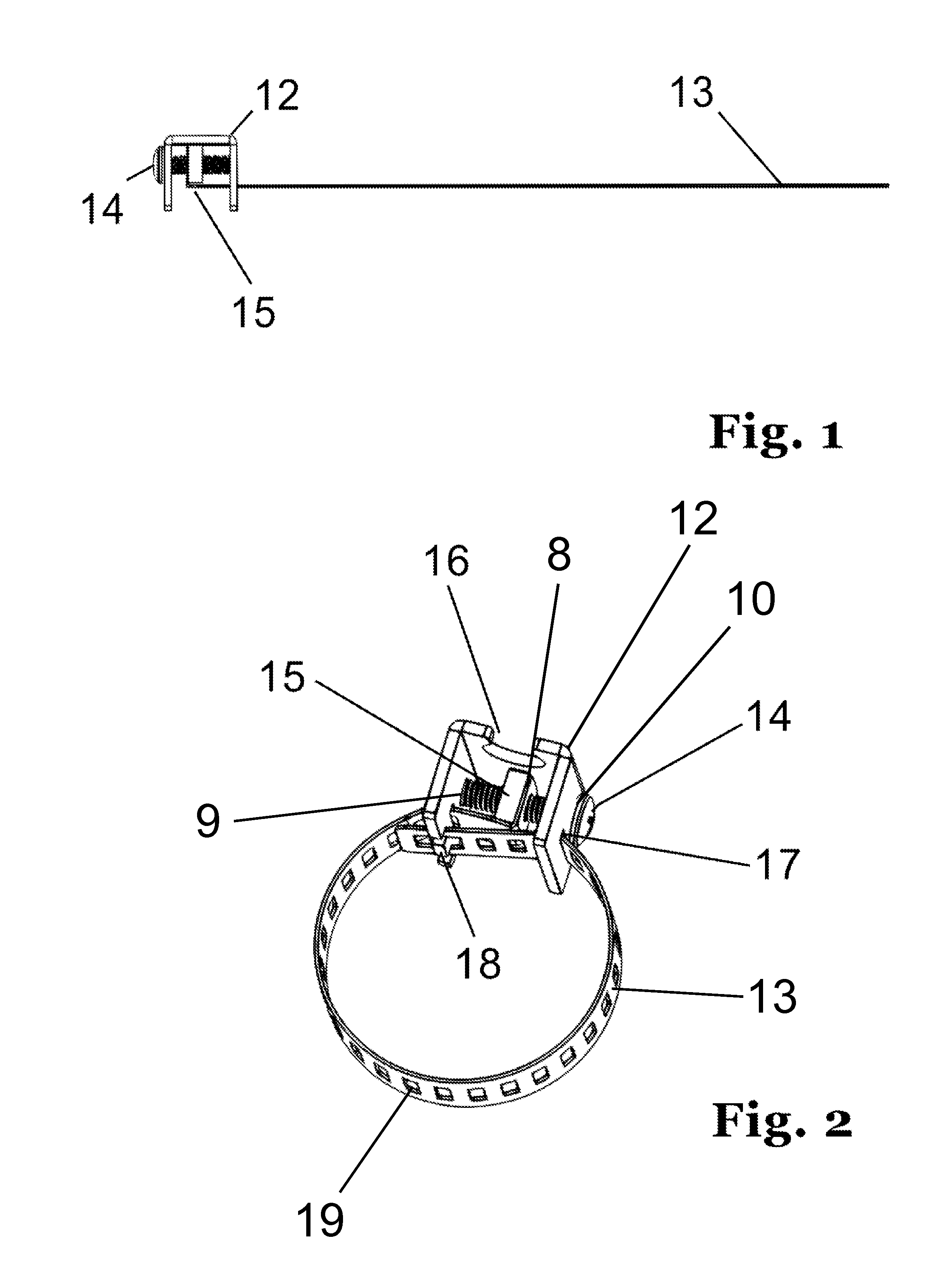
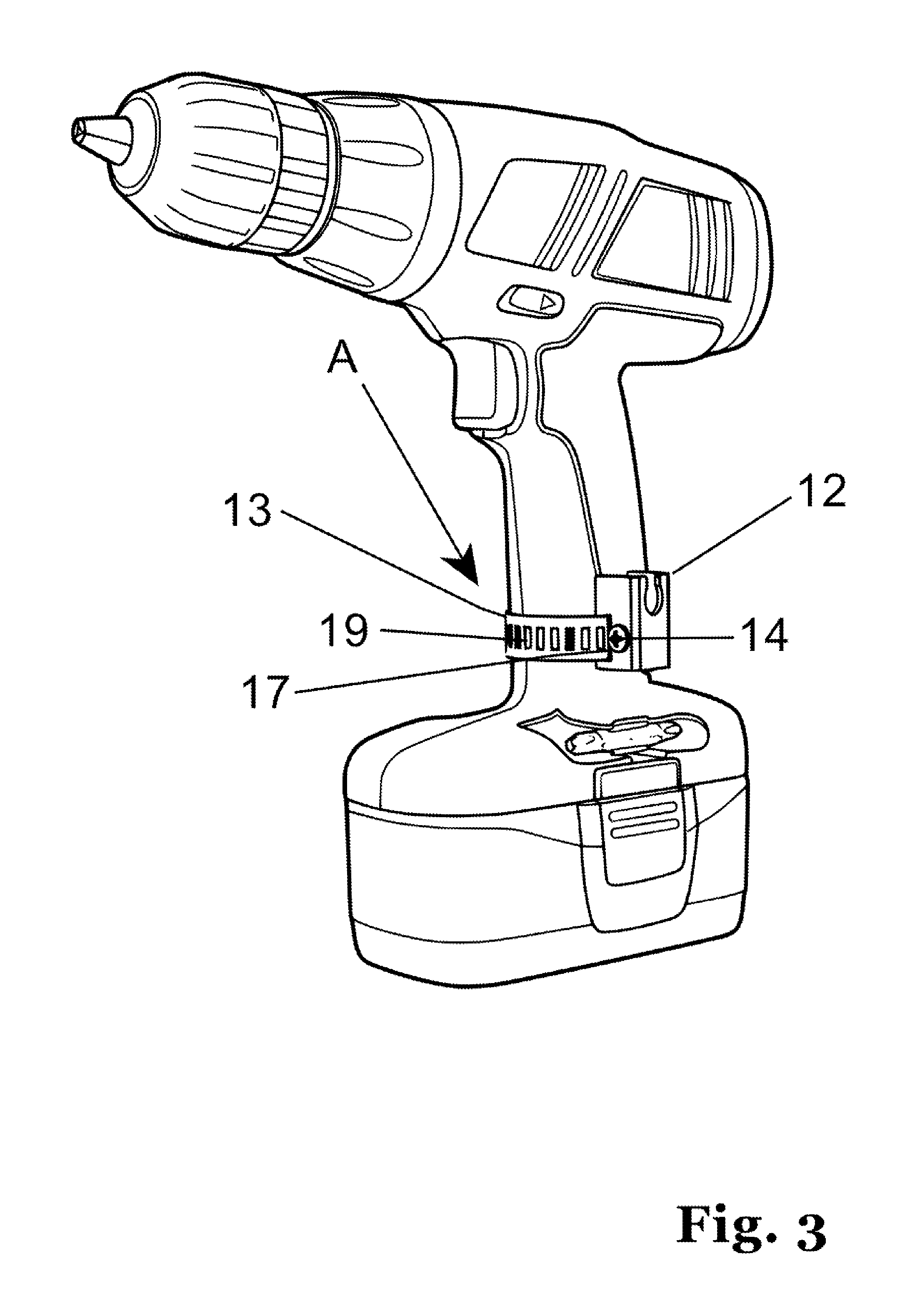
[0046]Referring now to FIGS. 1 & 2 showing two views illustrating the mechanical fastening device of the present invention. The mechanical fastening device of FIGS. 1 & 2 is comprised of several working parts. 12 is a bracket providing apertures sized to receive additional parts detailed herein. 13 is a flexible band providing spaced slots 19 of predetermined shape and size that passes through an aperture 11 in the bracket 12 and is mechanically held within the bracket 12. The bracket of FIGS. 1 & 2 also provides an aperture 17 that allows the loose end of the band 13 to pass through, and a flange 18 that allows one of the slots 19 of the band 13 to seat in it so that the band can be tightened when the other end is pulled. The other end can be pulled by turning the screw 14 so as to move the nut 15 against the flange 8 which tightens the band 13. The bracket 12 provides apertures 9&10 to receive an adjustment screw 14. The adjustment screw 14 engages ...


PUM


Abstract

A tool holding device is disclosed that securely but removeably holds tools such as cordless drills and nail guns to a tool user by means of a hook and or lanyard. The device is comprised of a belt mounted holder, a mechanical fastening device that is fastened to the handle of a tool, and a J-shaped hook that removeably attaches on one end to the handle mounted mechanical fastening device and on the other end to a belt mounted holder. This invention allows the tool user to securely hold their tools to themselves without endangering those working near by. The belt mounted holder provides a spring biased structure to secure itself to a belt or clothing as well as structure to securely receive one end of the J-shaped hook which can be removeably attached to the handle of a tool by the handle mounted mechanical fastening device attached to the other end.

Description

CROSS-REFERENCE TO RELATED APPLICATIONS[0001]This application claims the benefit of U.S. provisional patent application Ser. No. 61 / 743,530 filed on 2012 Sep. 6 by the present inventor.FEDERALLY SPONSORED RESEARCH[0002]Not applicableSEQUENCE LISTING OR PROGRAM[0003]Not applicableBACKGROUND OF THE INVENTION[0004]1. Field of Invention[0005]The present invention pertains to securing tools to promote convenient, as well as safe working conditions in various tool related industries. More precisely the present invention relates to a device that can be secured to most tools, allowing a multitude of safety devices and tool accessory devices to be secured to the tool.[0006]2. Prior Art[0007]A multitude of tool holding devices have been made available to the construction industry. For the most part these tool holders only work with a small subset of tools that are commonly used because of limited strength and limited range of adjustment on the portion that actually holds the tool. In general ...

Claims


Application Information

Patent Timeline
Patent Type & Authority Applications(United States)
IPC IPC(8): A45F5/02F16B45/00B25H3/00
CPCA45F5/02F16B45/00B25H3/006A45F5/021A45F2200/0575B25F5/029
Inventor WALSH, SEAN MICHAEL
Owner WALSH SEAN MICHAEL
Learn More