
Method of making a light-emitting-diode lamp tube

a technology of diodes and lamp tubes, which is applied in the manufacture of printed circuits, semiconductor devices for light sources, light and heating apparatuses, etc. it can solve the problems of mercury pollution, fluorescent lamps can be fragile, and the manufacturing process is simplified, so as to reduce labor costs and improve yield. the effect of significantly

Active Publication Date: 2014-04-10
JUSTING TECH
View PDF8 Cites 2 Cited by
  • Summary
  • Abstract
  • Description
  • Claims
  • Application Information

AI Technical Summary

Benefits of technology

The present invention provides a method for producing a light-emitting-diode lamp tube automatically, simplifying the manufacturing process and reducing labor costs while improving yield factors. The method includes steps such as providing a circuit board with an outbound circuit and an inbound circuit, printing a bonding layer on the circuit board, mounting electronic inserts with a connecting seat and light emitting diodes on the circuit board, heating up the circuit board to melt down the bonding layer, conducting a steps to assemble and fix the circuit board and translucent cover on a heat dissipation seat, providing an end cap with a conductive terminal, and connecting the conductive terminal with the connecting seat. The resulting lamp tube is efficient in heat dissipation and has improved performance and yield.

Problems solved by technology

In addition, if a person touches or adsorbs the mercury by accident, then he or she may be poisoned.
On the other hand, although a conventional fluorescent lamp is cheaper, its wastes can result in mercury pollution or the fluorescent lamp can be fragile.

Method used


Image

  • Method of making a light-emitting-diode lamp tube
  • Method of making a light-emitting-diode lamp tube
  • Method of making a light-emitting-diode lamp tube

Examples


Embodiment Construction

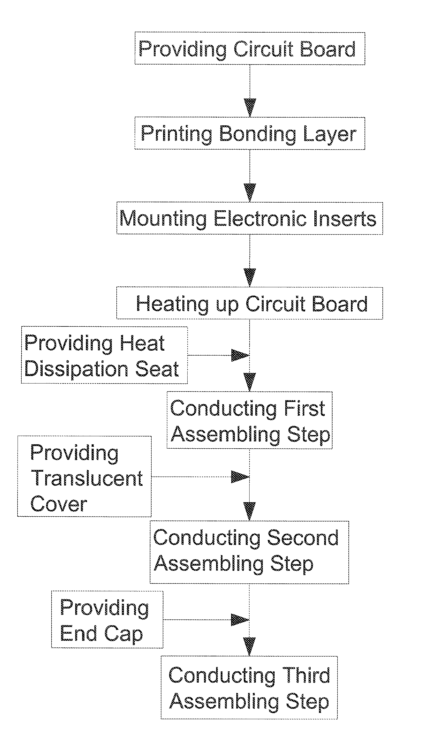
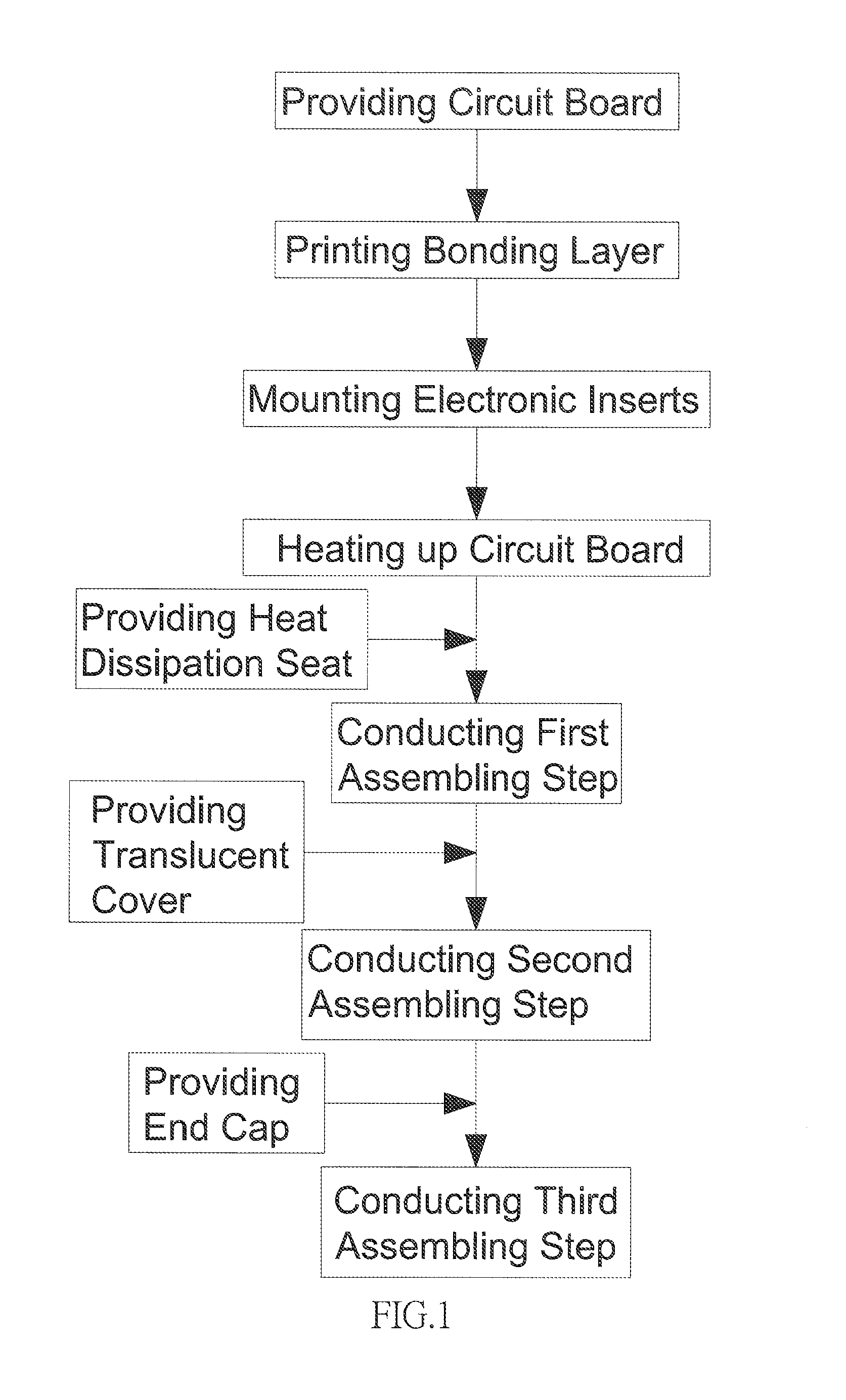
[0022]FIG. 1 discloses a flow diagram of a method of making a light-emitting-diode lamp tube, according to the present invention. The method of the present invention comprises following steps orderly.

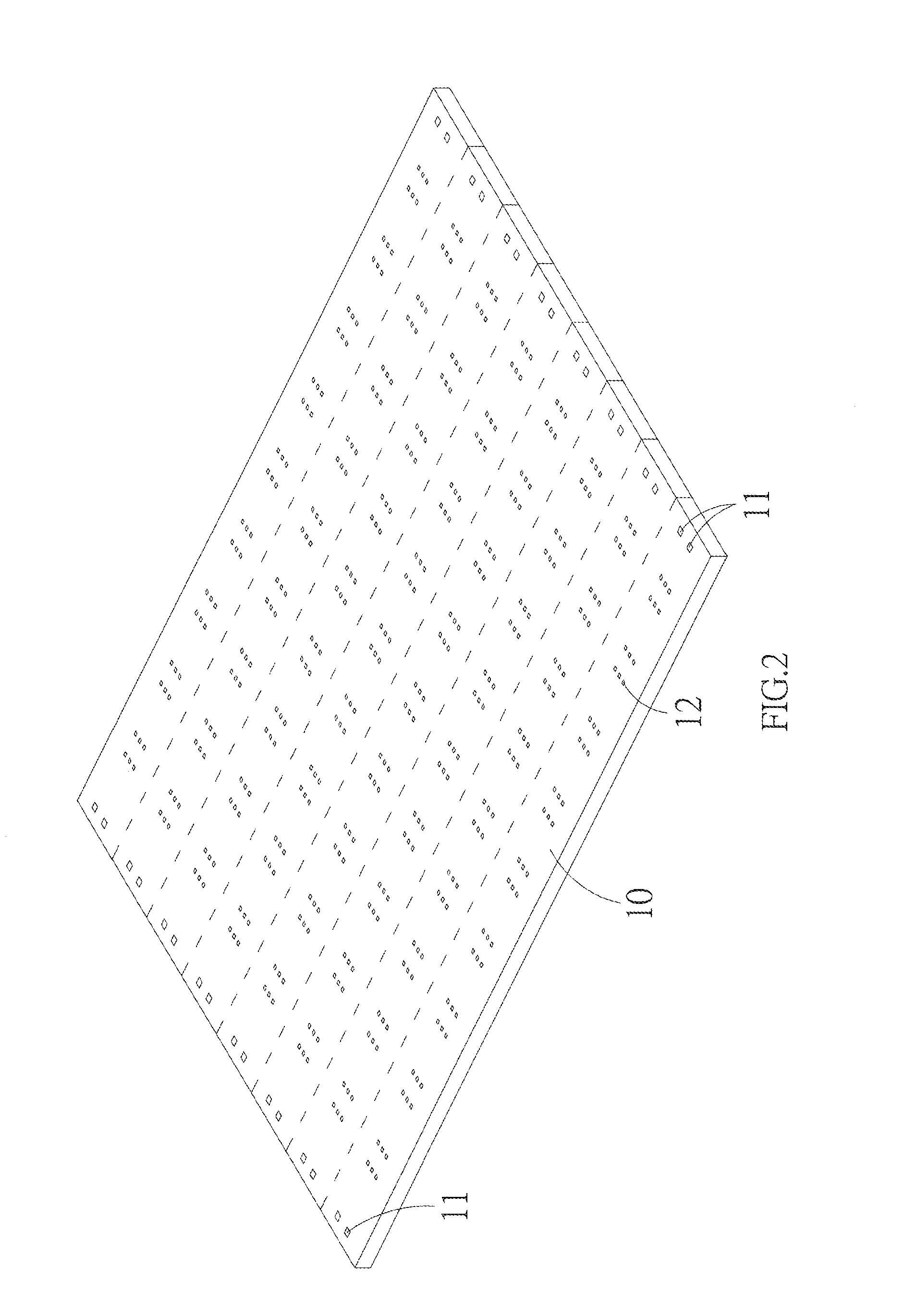
[0023]Step (A): providing a circuit board in a shape of a long strip. Referring to FIG. 2, the circuit board 10 is provided with an outbound circuit 11 and an inbound circuit 12, wherein the outbound circuit 11 is disposed in proximity to two end sides of the circuit board 10.

[0024]Step (B): printing. A bonding layer is printed on a surface of the outbound circuit and the inbound circuit of the circuit board, and the bonding layer can be a tin paste.

[0025]Step (C): mounting electronic inserts. Referring to FIG. 3, a connecting seat 20 is disposed on the outbound circuit 11 of the circuit board 10 where the bonding layer is provided, and light emitting diodes 30 are disposed on the inbound circuit 12 of the circuit board 10 where the bonding layer is provided, wherein the connecting seat...


PUM

PropertyMeasurementUnit
temperatureaaaaaaaaaa

Abstract

An automatic production method of making a light-emitting-diode lamp tube is disclosed. The method includes providing a circuit board in a shape of a long strip, printing a bonding layer, mounting electronic inserts, heating up the circuit board, assembling a heat dissipation seat, assembling a translucent cover and assembling an end cap, thereby accomplishing the lamp tube. By the abovementioned steps, the light-emitting-diode lamp tube can be produced automatically, the manufacturing process can be simplified to reduce the labor cost, and the yield factor can be improved considerably.

Description

BACKGROUND OF THE INVENTION[0001]a) Field of the Invention[0002]The present invention relates to a method of making a lamp tube, and more particularly to an automatic production method of making a light-emitting-diode lamp tube.[0003]b) Description of the Prior Art[0004]An early fluorescent lamp tube is mostly made of glass and contains small amount of mercury. Therefore, one should be very careful when taking or installing the fluorescent lamp tube; if the fluorescent lamp tube is broken accidentally, the mercury will flow out and damage the environment. In addition, if a person touches or adsorbs the mercury by accident, then he or she may be poisoned. On the other hand, although a conventional fluorescent lamp is cheaper, its wastes can result in mercury pollution or the fluorescent lamp can be fragile.[0005]For a new generation of the fluorescent lamp, an LED (Light Emitting Diode) is used to give out light, but the structure is still the same as the early design of the fluoresc...

Claims


Application Information

Patent Timeline
Patent Type & Authority Applications(United States)
IPC IPC(8): F21K99/00H05K3/30
CPCH05K3/30F21K9/90F21K9/27F21Y2103/10F21Y2115/10Y10T29/4913F21K9/275F21K9/272
Inventor SU, CHIA- CHINGYEN, CHIH-YUAN
Owner JUSTING TECH
Learn More