
System And Method For Tracking And Displaying Equipment Operations Data

a technology of equipment operations and system and method, which is applied in the field of system and method for tracking and displaying equipment operations data, can solve the problems of inability to achieve the effect of reducing the cost of fracture treatment, affecting the efficiency of fracture treatment,

Inactive Publication Date: 2014-04-03
SCHLUMBERGER TECH CORP
View PDF10 Cites 109 Cited by
  • Summary
  • Abstract
  • Description
  • Claims
  • Application Information

AI Technical Summary

Benefits of technology

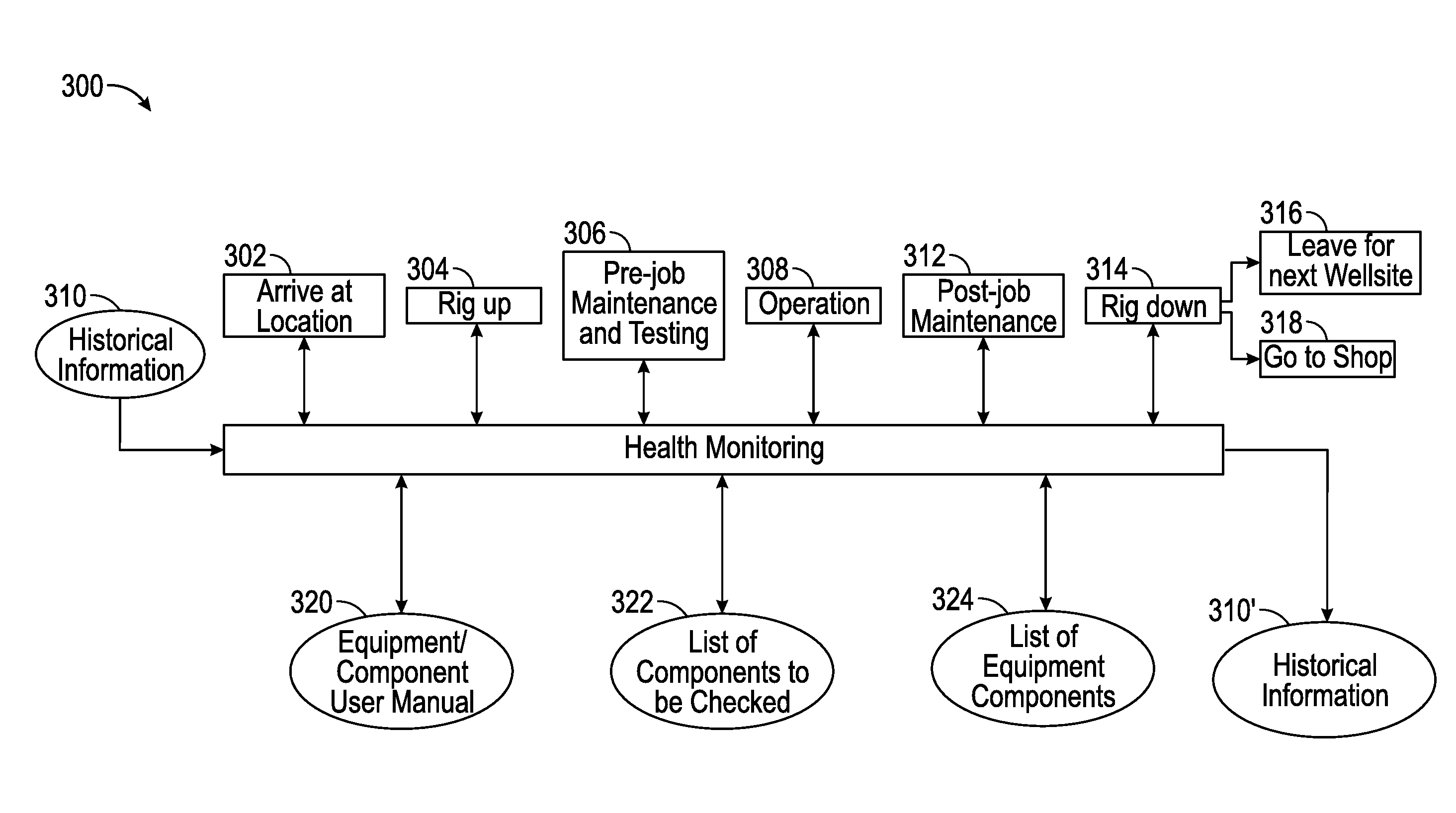
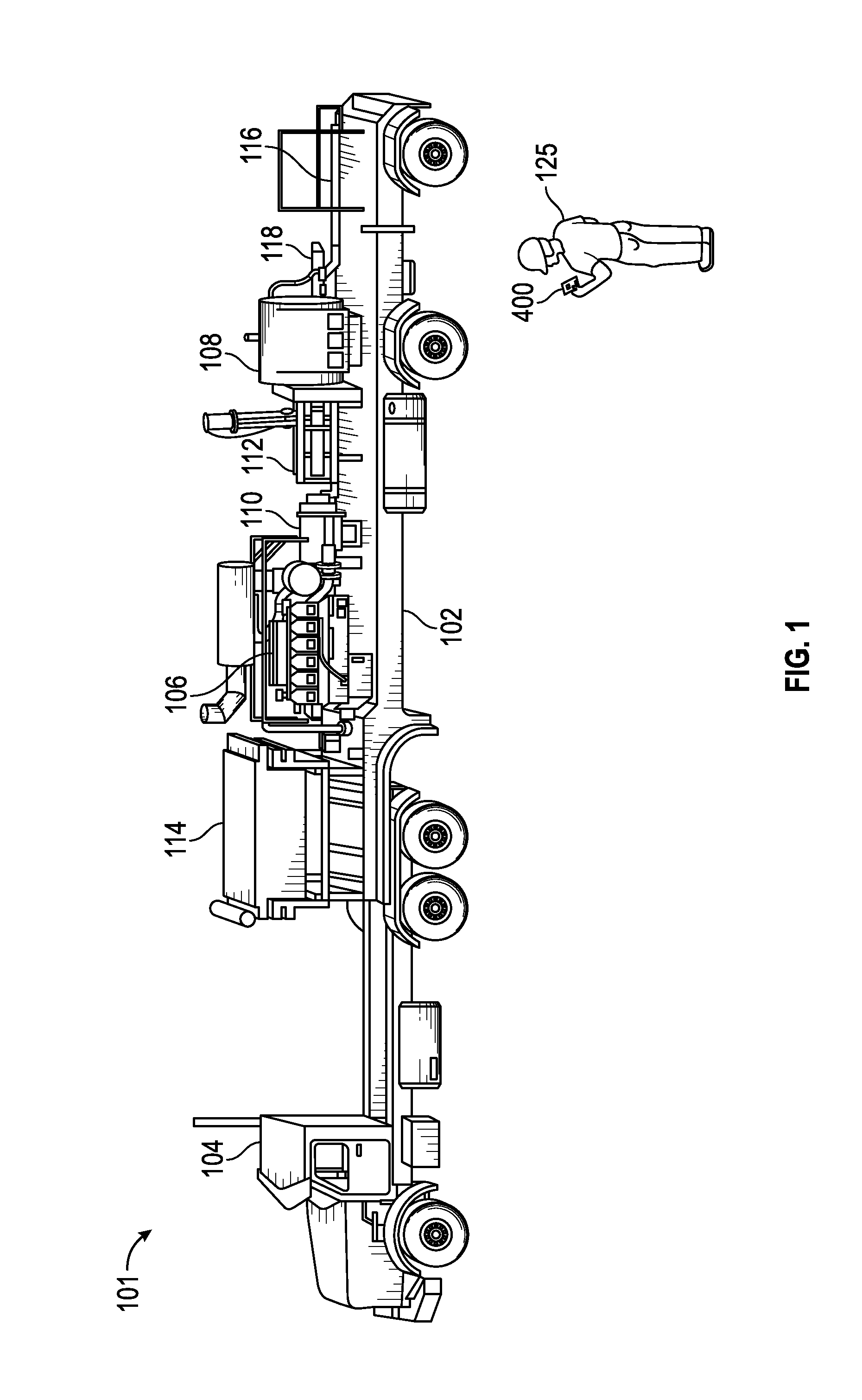
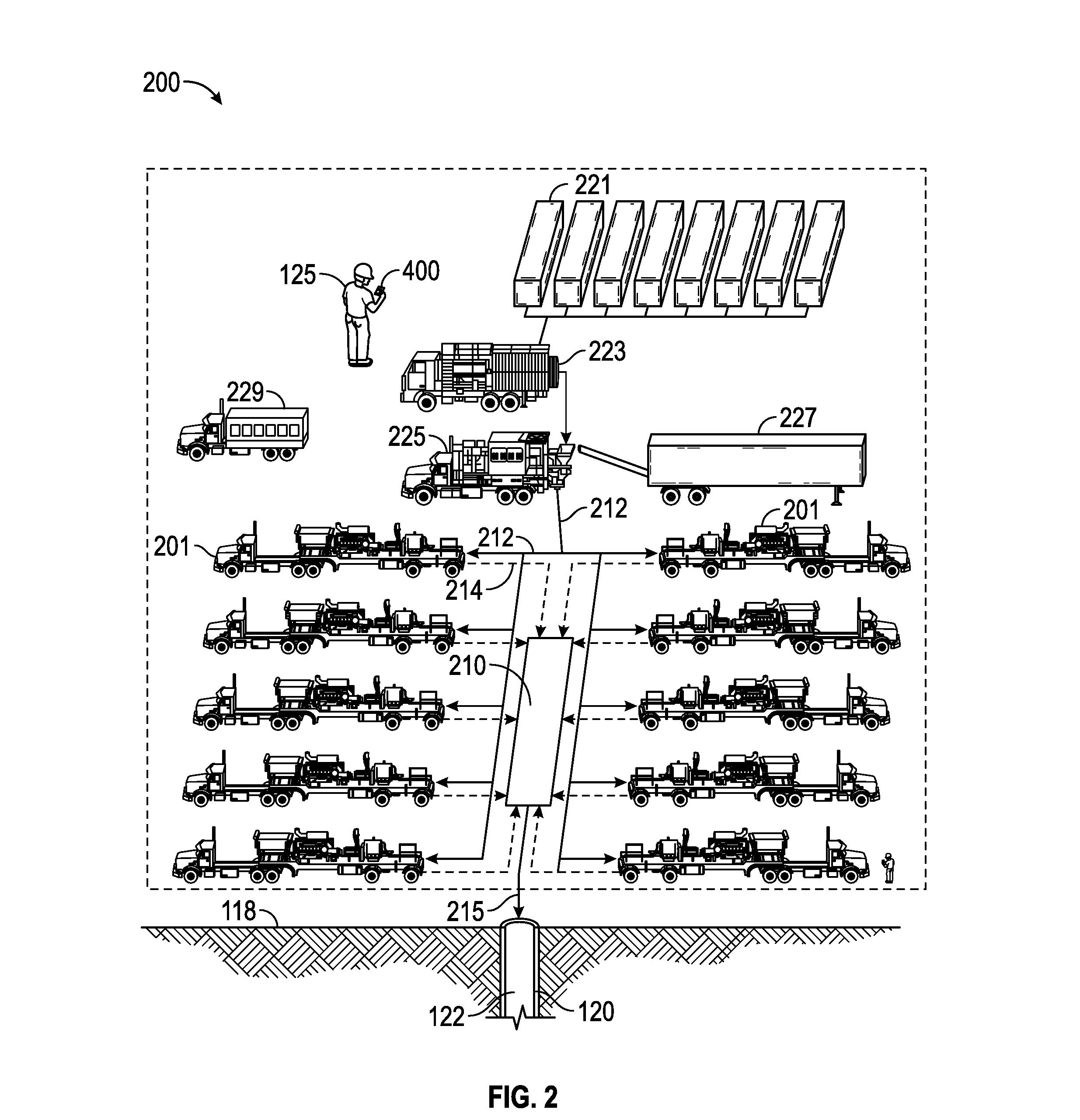
This patent describes a system that allows for real-time monitoring and management of equipment at a worksite. The system includes multiple equipment units and a central hub. The equipment units have a processor and computer-readable medium with instructions for translating equipment operations data and generating indicators of logs and log entries. The central hub has a separate database and synchronizes with the equipment units to store the logs. The management terminal has a processor and access to the databases, displaying real-time data on the equipment's operating status. The technical effect of this system is the ability to quickly detect and address equipment issues at a construction or drilling site, improving efficiency and safety.

Problems solved by technology

The proppant is a particulate material added to the pumped fluid to produce slurry, which is often very abrasive and / or corrosive.
Pumping this slurry at the appropriate flow rate and pressure may be a severe pump duty.
Since fracturing operations are desirably conducted on a continuous basis, the disruption of a fracture treatment because of a failure of surface equipment is costly, time consuming, inefficient, and unproductive.
Further, when such massive pumps are used, it is difficult in some instances to determine, in the event of a pump failure, which pump has failed.
Because of the severe pump duty and the frequent failure rate of such pumps, it is normal to take thirty to one hundred percent excess pump capacity to each fracture site.
The excess pump capacity may take additional capital to acquire the additional multiplex pumps and considerable expense to maintain the additional pumps and to haul them to the site.
Sometimes, the maintenance data is not communicated to the central data location or gets lost during transmission.
One prominent issue associated with the traditional method is that the data capturing and transmitting process is not automated and any breakdown in the process may cause delay or failure to the equipment.
Another problem with the conventional method is that it is not uniformly executed across operations; therefore, the data received at the center may be corrupted or missing information.
When the maintenance data is incomplete or inaccurate, it is difficult for the management to determine what maintenance is needed, when maintenance is needed, and which equipment (or a component of equipment) on which maintenance should be performed, where the equipment is currently located, which location(s) the equipment has been deployed in its life, etc.
However, fracturing operations are often conducted in geographically remote areas, which may have poor or no connectivity to a communications network.
Where fracturing operations are able to access a communications network, the connectivity to the communications network may be unreliable or have low data transmission rates.
Unreliable connections may lead to loss of data or data corruption during transmission of the data across the network.
The resulting loss of data and data corruption may create gaps within the operations data viewed for management purposes and archival purposes.
Low transmission rates may inhibit the types and amount of data transmitted across the unreliable communications network.

Method used


Image

  • System And Method For Tracking And Displaying Equipment Operations Data
  • System And Method For Tracking And Displaying Equipment Operations Data
  • System And Method For Tracking And Displaying Equipment Operations Data

Examples


Embodiment Construction

[0033]Specific embodiments of the present disclosure will now be described in detail with reference to the accompanying drawings. It is to be understood that the various embodiments, although different, are not necessarily mutually exclusive. For example, a particular feature, structure, or characteristic described herein in connection with one embodiment may be implemented within other embodiments without departing from the spirit and scope of the present disclosure. Further, in the following detailed description of embodiments of the present disclosure, numerous specific details are set forth in order to provide a more thorough understanding of the present disclosure. However, it will be apparent to one of ordinary skill in the art that the embodiments disclosed herein may be practiced without these specific details. In other instances, well-known features have not been described in detail to avoid unnecessarily complicating the description.

[0034]It should also be noted that in th...


PUM


Abstract

A maintenance terminal unit is provided with a processor and a computer readable medium coupled to the processor. The computer readable medium is non-transitory and local to the processor. The computer readable medium stores computer executable instructions, that when executed by the processor cause the processor to: (1) receive equipment operations parameter data indicative of an operating status of a plurality of equipment, wherein separate equipment operations parameter data is received for at least two of the plurality of equipment; (2) translate the equipment operations parameter data relative to at least one threshold level into management operations data; (3) generate indicia of logs for the plurality of equipment; (4) generate indicia of log entries for the plurality of equipment; and (5) display indicia of the logs and log entries. The equipment can be wellsite equipment located at a wellsite.

Description

BACKGROUND[0001]The statements made herein merely provide information related to the present disclosure and may describe some embodiments illustrating the invention.[0002]Embodiments disclosed herein generally relate to systems or methods for facilitating, capturing, tracking, synthesizing, analyzing, managing and / or utilizing maintenance data for equipment, and in particular, but not limited to, systems or methods for facilitating, capturing, tracking, synthesizing, analyzing, managing and / or utilizing wellsite maintenance data for wellsite equipment. Embodiments disclosed herein also relate to systems or methods for determining degradation conditions of equipment or predicting residual life of equipment before, during, and after an oilfield operation. Examples of such oilfield operations include, but are not limited to, hydraulic fracturing, acid stimulation, cementing, etc.[0003]In some embodiments, the equipment being maintained includes positive displacement pumps, sometimes re...

Claims


Application Information

Patent Timeline
IPC IPC(8): G06F17/40
CPCG06Q10/20
Inventor THOMEER, HUBERTUS V.FAUGHT, EDWIN GUYCAPPS, KAY STEFANMARSHALL, KYLE CHARLES
Owner SCHLUMBERGER TECH CORP
Learn More