
Submerged combustion melters having an extended treatment zone and methods of producing molten glass

a technology of submerged combustion and melters, which is applied in the direction of furnaces, tank furnaces, manufacturing tools, etc., can solve the problems of large turbulence, lack of melter footprint or size, and rapid melting of glass batches

Active Publication Date: 2014-04-03
JOHNS MANVILLE CORP
View PDF3 Cites 67 Cited by
  • Summary
  • Abstract
  • Description
  • Claims
  • Application Information

AI Technical Summary

Benefits of technology

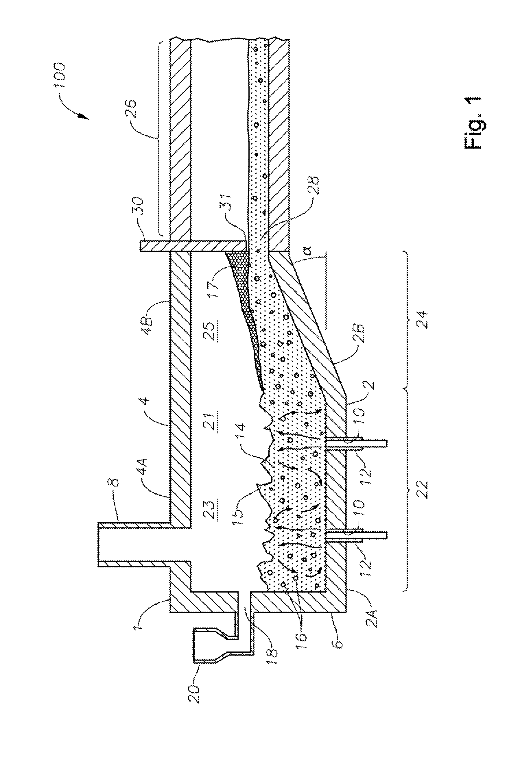
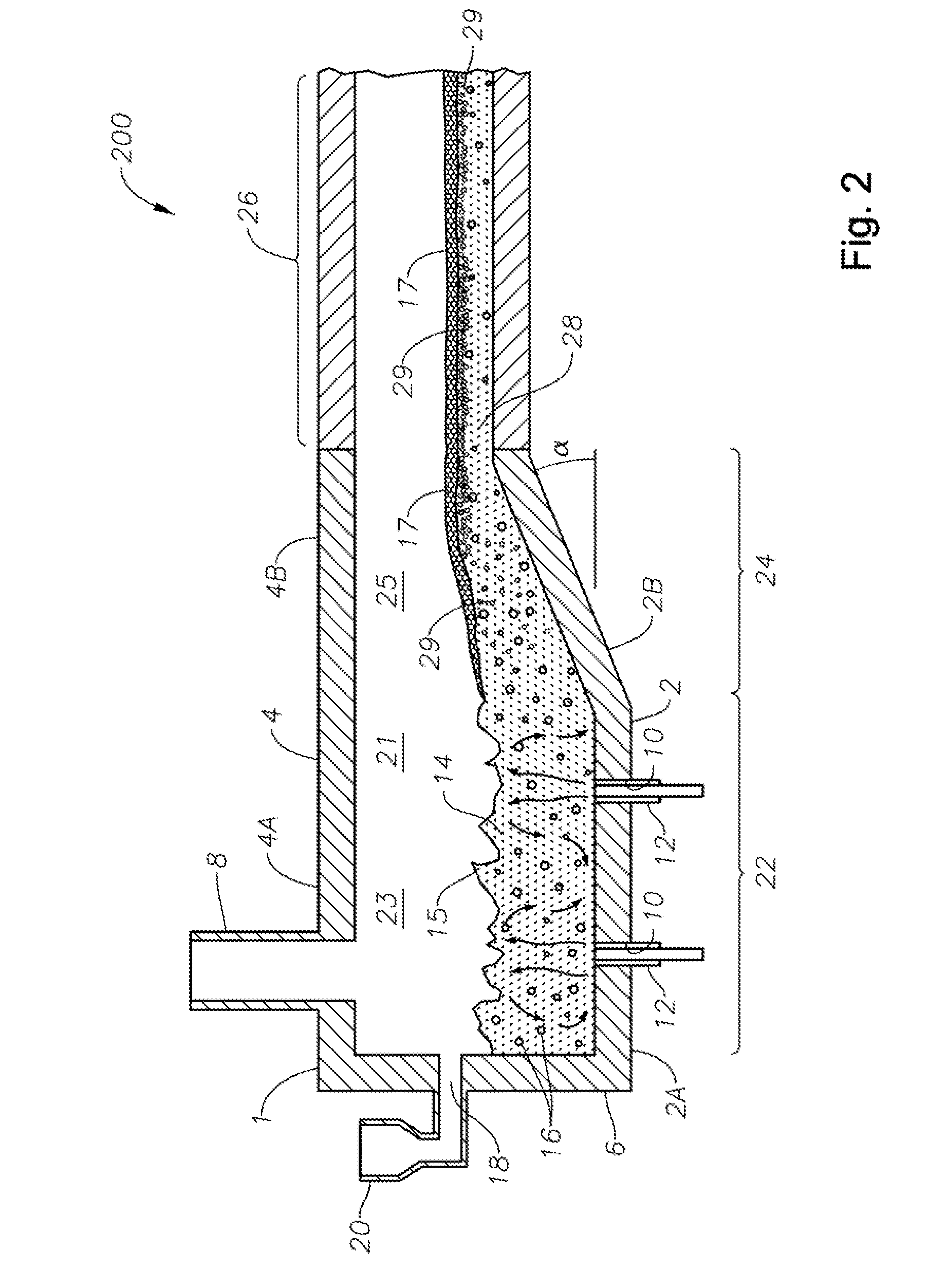
The present disclosure describes submerged combustion melters and processes that address various problems associated with traditional melting processes. The melter has a unique geometry that reduces turbulence and increases the level of molten glass in the melting and fining zones, while the combustion burners are positioned away from these zones to avoid increasing turbulence. The melter also includes a floor, roof, and sidewall structure, with a melting zone, a fining zone, a treating zone, and a feed zone. The process involves charging a feed composition into the melter, heating it with submerged combustion burners, allowing the molten glass to flow through the melting and fining zones, and maintaining a level of molten glass in each zone. The submerged combustion melter and process provide a more efficient and controlled method for producing glass.

Problems solved by technology

The introduction of high flow rates of oxidant and fuel into the molten glass, and the expansion of the gases cause rapid melting of the glass batch and much turbulence, and possibly foaming.
Although this is still desired for the most part, one drawback to this strategy in known SCMs is the lack of, or total absence of melter footprint or size outside of the submerged combustion melting zone that might provide some time downstream of the melting zone for treatment of the turbulent, foamy molten glass before it enters downstream equipment.
Furthermore, there typically is a lack of, or no melter footprint before the melting zone of an SCM.
These failings may severely limit the flexibility of operation of an SCM.
The foam layer may impede the ability to apply heat to the glass using combustion burners to achieve or maintain temperature and compositional homogeneity of the molten glass, and may also impede the rate at which further bubbles in the melt rise and thus affect expulsion of the bubbles and mass flow rate of the melt in the channels.
In extreme cases, the foam generated may interfere with the traditional energy application methods employed, which may cause systems to require shutdown, maintenance and may result in a process upset.
Attempts to reduce the foam through process adjustments have not met with complete success in reducing foam to an acceptable amount.
On the other hand, in cases where foaming may be desired, control of bubble size, composition, and the like may be hindered in smaller footprint SCMs.

Method used


Image

  • Submerged combustion melters having an extended treatment zone and methods of producing molten glass
  • Submerged combustion melters having an extended treatment zone and methods of producing molten glass
  • Submerged combustion melters having an extended treatment zone and methods of producing molten glass

Examples


Embodiment Construction

[0036]In the following description, numerous details are set forth to provide an understanding of the disclosed systems and methods. However, it will be understood by those skilled in the art that the systems and methods covered by the claims may be practiced without these details and that numerous variations or modifications from the specifically described embodiments may be possible and are deemed within the claims. All U.S. published patent applications and U.S. patents referenced herein are hereby explicitly incorporated herein by reference. In the event definitions of terms in the referenced patents and applications conflict with how those terms are defined in the present application, the definitions for those terms that are provided in the present application shall be deemed controlling.

[0037]As explained briefly in the Background, one drawback to present submerged combustion melters is the lack of, or total absence of melter footprint or size outside of the submerged combusti...


PUM

PropertyMeasurementUnit
Fractionaaaaaaaaaa
Massaaaaaaaaaa
Depthaaaaaaaaaa

Abstract

A submerged combustion melter includes a floor, a roof, and a sidewall structure connecting the floor and roof defining an internal space. A first portion of the internal space defines a melting zone, and a second portion defines a fining zone immediately downstream of the melting zone. One or more combustion burners in either the floor, roof, the sidewall structure, or any combination of these, are configured to emit the combustion gases from a position under a level of, and positioned to transfer heat to and produce, a turbulent molten mass of glass containing bubbles in the melting zone. The fining zone is devoid of combustion burners or other apparatus or components that would increase turbulence above that in the melting zone. The melter may include a treating zone that stabilizes or destabilizes bubbles and / or foam. Processes of using the melters are a feature of the disclosure.

Description

CROSS-REFERENCE TO RELATED APPLICATIONS[0001]This application may be related to the following United States non-provisional patent applications assigned to the assignee of the present application which are all incorporated by reference herein: U.S. Ser. No. 12 / 817,754, filed Jun. 17, 2010; U.S. Ser. Nos. 13 / 267,990, 13 / 268,028, 13 / 268,098, and 13 / 268,130, all four filed Oct. 7, 2011; U.S. Ser. No. 13 / 458,211, filed Apr. 27, 2012; U.S. Ser. Nos. 13 / 493,170 and 13 / 493,219, both filed Jun. 11, 2012; U.S. Ser. No. 13 / 540,771, filed Jul. 3, 2012. U.S. patent applications identified as Attorney Docket Nos. 8144-1, 8144-2, 8147 and 8161 are being filed on even date herewith.BACKGROUND INFORMATION[0002]1. Technical Field[0003]The present disclosure relates generally to the field of combustion furnaces and methods of use to produce glass, and more specifically to submerged combustion melters and methods for producing foamed glass, hollow or entrained-gas fiber, or non-foamed glass using the ...

Claims


Application Information

Patent Timeline
IPC IPC(8): C03B5/225
CPCC03B5/04C03B5/193C03B5/20C03B5/205C03B5/225C03B5/2356C03B2211/22C03B2211/23C03B2211/24Y02P40/50C03B5/173
Inventor CHARBONNEAU, MARK WILLIAMMCHUGH, KEVIN PATRICKHUBER, AARON MORGAN
Owner JOHNS MANVILLE CORP
Learn More