
Hydraulic Device for the Injection of Bone Cement in Percutaneous Vertebroplasty

a percutaneous vertebroplasty and hydraulic device technology, applied in the medical field, can solve the problems of reducing the life expectancy, deteriorating the quality, and insufficient manual pressure, so as to reduce the overexposure of the operator to ionizing radiation, reduce the time loss, and slow down the solidification time

Inactive Publication Date: 2014-03-27
DEPUY SYNTHES PROD INC
View PDF1 Cites 20 Cited by
  • Summary
  • Abstract
  • Description
  • Claims
  • Application Information

AI Technical Summary

Benefits of technology

Enables controlled and efficient injection of bone cement at a safe distance from the radiation source, reducing operator exposure to ionizing radiation, minimizing cement leakage, and ensuring complete delivery of the required volume while preventing premature solidification.

Problems solved by technology

In this group of advanced age, the immobilization resulting from vertebral fractures has severe consequences in their general medical conditions, it predisposes them to cardiopulmonary, intestinal, circulatory complications, etc.
Besides pain, the psychological effects can be devastating, it deteriorates the quality and reduces the expectation of life.
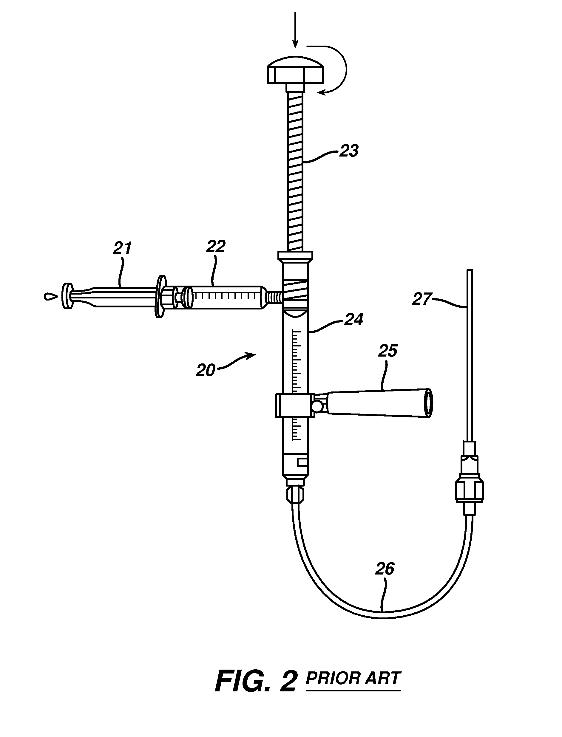
If larger diameter syringes are used, the manual pressure is insufficient due to the density and viscosity of the bone cement; and becomes necessary the employment of a mechanical device to be able to exercise the required pressure.
In most of these devices the syringe is not interchangeable, it is loaded with the total volume to inject and therefore, are of larger diameter and the increased resistance to the flow of the cement becomes worse with time due to solidification of cement.
On the other hand, the conventional hypodermic syringes are not designed for high pressure injection, the plunger and the fingers supporting wings bend easily.
They don't allow the operator to maintain an appropriate distance to reduced exposure to secondary radiation at acceptable levels according with the international radiological protection norms.
On the other hand, some mechanical devices do not allow control or manual sensibility of the exercised pressure and speed of the injection of the cement, important factors in the prevention of undesirable leaks and complications.
On the other hand, due to the viscosity of the cement and quantity keeps certain dynamic memory that doesn't allow sudden interruption of the injection.
Although this device provides control in the injection of the bone cement, the operator is too near the patient.
These mechanisms with big deposits have the inconvenience that the cement can end up solidifying in the conduit at the time of application and impede to apply the total amount of cement inside the affected vertebral body.
On the other hand, with the excess of pressure generated by these devices, the cement could leak outside of the vertebral body, since the fluid (PMMA), for its viscosity, possesses a remaining flowing memory that may be difficult to control.
Another inconvenience is that if the cement solidifies in the system and has not reached the vertebral body in the proper amount, it is necessary to make another preparation previous placement of another needle in a different and appropriate position for the new requirement.
This device has the inconvenience that one doesn't have manual sensitivity and control of the pressure exercised, it is not easy to exchange the syringes with the bone cement.

Method used


Image

  • Hydraulic Device for the Injection of Bone Cement in Percutaneous Vertebroplasty
  • Hydraulic Device for the Injection of Bone Cement in Percutaneous Vertebroplasty
  • Hydraulic Device for the Injection of Bone Cement in Percutaneous Vertebroplasty

Examples


Embodiment Construction

[0040]The present describes a new device and method to treat affections of the bones, specifically, in the treatment of osteoporotic or fractured vertebral bodies,

[0041]These bone structures have different pathological states of diverse ethiology (trauma, osteoporosis, primary bone tumors or metastases, etc.). An alternative of treatment to stabilize and to consolidate this structures consists on the injection of a bio-materials such polymethylmethacrylate in the interior of the vertebral body for healing purpose.

[0042]The injection of biomaterials such as bone cement is carried out by means of a hydraulic device exerting pressure on small caliber conventional syringes connected directly to the needle; since the cement has the property of becoming hard quickly.

[0043]The theoretical basic principle for the operation of the device of the present invention consists on the amplification of the hydraulic pressure generated at distance and transmitted by the hydraulic tube.

[0044]In refere...


PUM


Abstract

The present invention relates to the medical field, in particular relates to the practice of percutaneous vertebroplasty where a pair of syringes in the distal extreme of a lengthened hydraulic device, are united by a camera of intermediate connection of larger diameter (pressure exerting body) or modified inverted syringe tube with a bolster, a hydraulic connecting tube of flexible material that transmits the pressure of the smaller diameter manual or impulsion syringe in the proximal extreme of the device toward the intermediate cylindrical larger diameter camera (pressure exerting body), this camera is in an inverted position with regard to the first syringe (fluid control), this intermediate camera has a moving piston longitudinal to the axis of the cylinder that is controlled with the first syringe (manual) and in cooperation with the atmospheric pressure. The injecting syringe loaded with bone cement is coupled with the bolster of the body of pressure, and to the needle that drives the cement toward the interior of the bone. The intermediate camera (pressure exerting body) together with the hydraulic tube and the manual syringe form a hydraulic press system (F / A=f / a) that allows to increase in a potential way the pressure exerted in the first syringe and to make the injection of polymethylmethacrylate (PMMA) at an approximate distance of 1.0 m to 1.5 m.

Description

CROSS-REFERENCE TO RELATED APPLICATIONS[0001]This application the National Phase Application of International Application No. PCT / MX2003 / 000027 filed Mar. 14, 2003.TECHNICAL FIELD[0002]This invention in a general way relates to the medical area in procedures where it is required to inject a dense or viscous fluid through a needle, in a particular way the viscous material is the polymethylmethacrylate. it is used in procedures like percutaneous vertebroplasty, kyphoplasty or other surgical events of the field. It has applications in other areas where it is required to apply at distance a dense and viscous liquid.BACKGROUND OF THE INVENTION[0003]Percutaneous vertebroplasty is a minimally invasive interventional radiological procedure that consists on injecting bone cement (Polymethylmethacrylate, PMMA) in the vertebral body, by trans-pedicular or oblique approach through a bone biopsy needle.[0004]It was developed in France in 1984 for the treatment of aggressive or painful haemangiom...

Claims


Application Information

Patent Timeline
Patent Type & Authority Applications(United States)
IPC IPC(8): A61B17/88A61B17/00A61F2/46A61M5/315
CPCA61B17/8819A61B17/00234A61F2002/4635A61M5/31511A61M5/31586A61B17/8822
Inventor FERREYRO, ROQUE HUMBERTOMIRANDA, MARIO MARQUEZ
Owner DEPUY SYNTHES PROD INC
Learn More