
Vibrating Surgical Device for Removal of Vitreous and Other Tissue

a surgical device and vitreous technology, applied in the field of vitreous surgical device for the removal of vitreous and other tissue, can solve the problems of reducing the flow rate below the surgically desirable level, affecting other structures, and affecting the operation. effect of operation

Active Publication Date: 2014-03-13
BAUSCH & LOMB INC
View PDF7 Cites 53 Cited by
  • Summary
  • Abstract
  • Description
  • Claims
  • Application Information

AI Technical Summary

Benefits of technology

The patent describes an ophthalmic surgical device that includes a housing with a distal end and a proximal end. The device has a cannula attached to the housing with a distal tip having at least one port in communication with a lumen extending through the cannula. The device also includes a vibration source for vibrating the cannula to assist in vitreous and other tissue removal from the eye. The device creates a periodic bi-directional flow of tissue through the port without creating cavitation externally of the distal tip. The patent also describes an ophthalmic surgical kit comprising multiple entry site alignment devices and infusion cannulas for insertion into the eye. The infusion cannulas provide more cross-sectional area for infusion fluid than the port of the tissue extraction device. The patent also describes an ophthalmic surgical system that includes a vitreous cannula for removing vitreous and other tissue from the eye. The system includes multiple entry site alignment devices for insertion into the eye and an infusion cannula for infusing fluid into the eye.

Problems solved by technology

The vitreous fibers or strands are anchored to the vitreous membrane (or hyaloid membrane) which rests, in part, next to the retina—pulling on the vitreous membrane can cause optical distortions or even damage to the retina as the vitreous membrane pulls away from the retina.
That is, a small portion will get drawn into the hole, pulling along a larger portion which will not fit through the hole, thereby clogging it.
Second, even if, by using a large enough hole and a strong enough vacuum, some vitreous was successfully pulled into the aspirating device, the sticky nature of the vitreous would grab an inner wall of the aspirating device, reducing flow rates below surgically desirable levels.
Third, even if a continuous flow were established for a short period of time, the ends of the vitreous strands not yet pulled through the hole will continue to pull material toward them, eventually pulling on and damaging other structures such as the hyaloid membrane or the retina; this is colloquially referred to as “traction” by retinal surgeons.
If the surgeon attempts to remove the vitreous with either the ultrasonic device using the lens removal tip or an irrigation / aspiration handpiece using the capsule polishing tip, the handpiece needles become clogged by the sticky vitreous and generate traction on the elements in the posterior section of the eye (for the reasons noted above) and become ineffective.
Slow removal of vitreous means longer surgical times, which are stressful for the patient and the patient's eye.
Large wounds require stitches across the wound for closure, potentially causing discomfort and optical distortion.
Mechanical retinal damage may result in blind spots or chronic vision degradation.
High infusion pressures may restrict blood flow to the retina, potentially causing permanent damage to the retina.
Fluctuations in intraocular pressure may cause tissue to move into the mouth of the cutter inadvertently, or cause the eye to collapse momentarily.
Furthermore, it is possible for bubbles to form at the tip of an ultrasonic cannula when brought into contact with vitreous thereby obscuring vision of the surgical site and adversely affecting the fluidics within the eye.
These bubbles, commonly referred to as cavitation, also may damage tissue not intended to be damaged.
These objectives may conflict with each other.
Low infusion pressures provide less safety margin for intraocular pressure fluctuation.
A further complicating factor is that vitreous flow for a given pressure differential is generally lower than water flow; and vitreous and water are hard to distinguish visually during surgery, as they are both transparent.
There have been patents and scientific articles that mention removing vitreous with an ultrasonic device but none have taught how to safely and reliably remove vitreous without traction during surgery.
. . to create a vacuum to aspirate the ocular tissue”, or aspiration without assistance of an aspiration pump, which could result in unacceptably low flow rates.
However, no attempt was made to aspirate the vitreous out of the chamber through the device.
The oscillating cutters are not used because of potential traction problems from uncut vitreous (“spooling”) that could cause damage to the retina.
This means that the vitreous pieces will drag the inner needle walls and may, from time to time, jam together as they flow up the tube.
This increases the flow resistance and the likelihood of clogs, while also decreasing the effective flow rate.
All mechanical vit cutters rely on some level of interference between the inner needle and the outer needle due to bending or displacement of the inner needle; this interference adds drag, which slows down the inner needle, and makes higher cut rates harder to achieve.
These abrupt flow changes require higher infusion pressures to manage the intraocular pressure, and potentially could cause damage to the structures in the eye.
Although partially effective, all the prior art vitreous removal devices fail to fully realize the end goals of small wound size, high flow, and low traction.

Method used


Image

  • Vibrating Surgical Device for Removal of Vitreous and Other Tissue
  • Vibrating Surgical Device for Removal of Vitreous and Other Tissue
  • Vibrating Surgical Device for Removal of Vitreous and Other Tissue

Examples


Embodiment Construction

[0065]Example embodiments will now be described more fully with reference to the drawings.

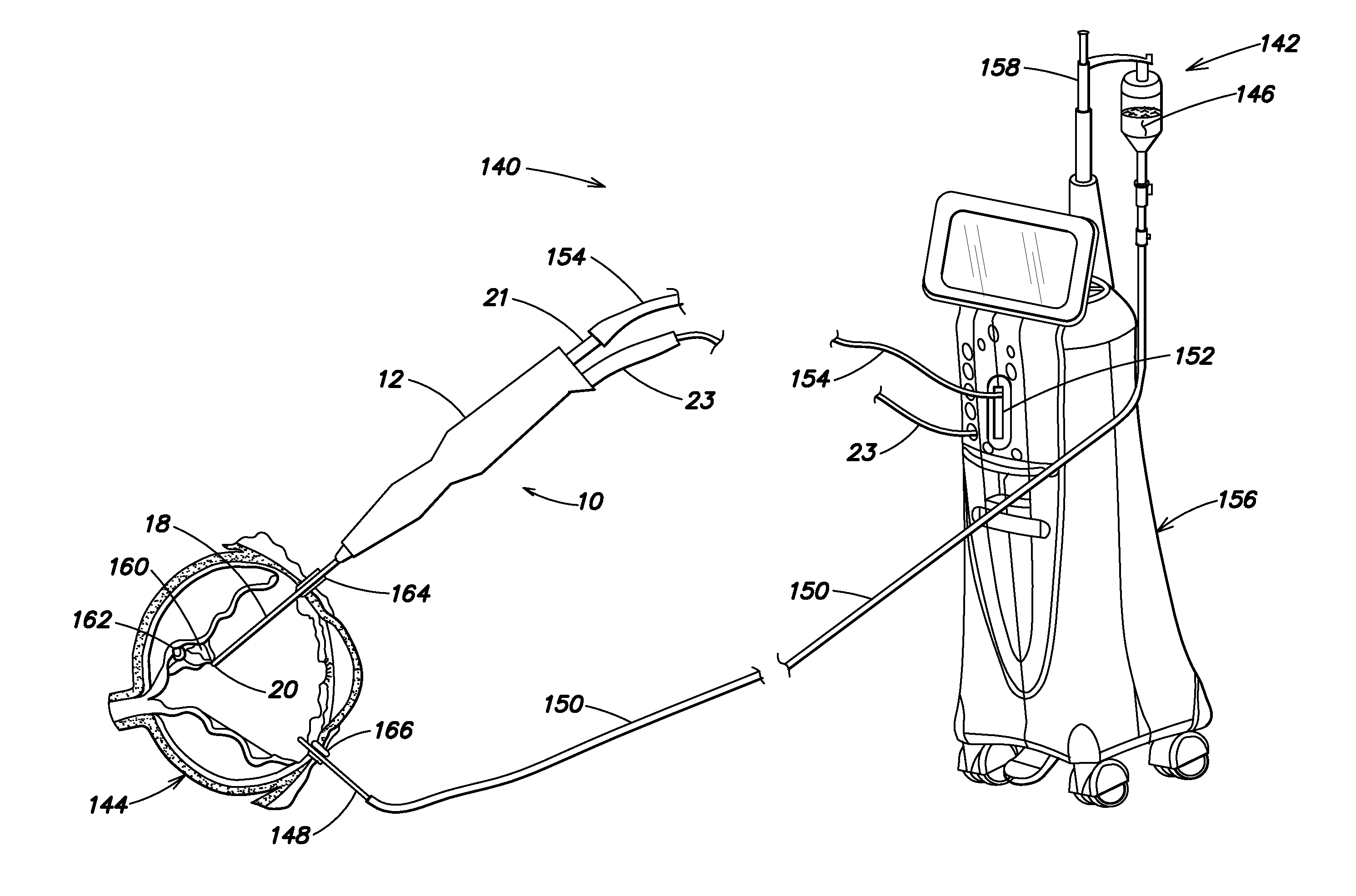
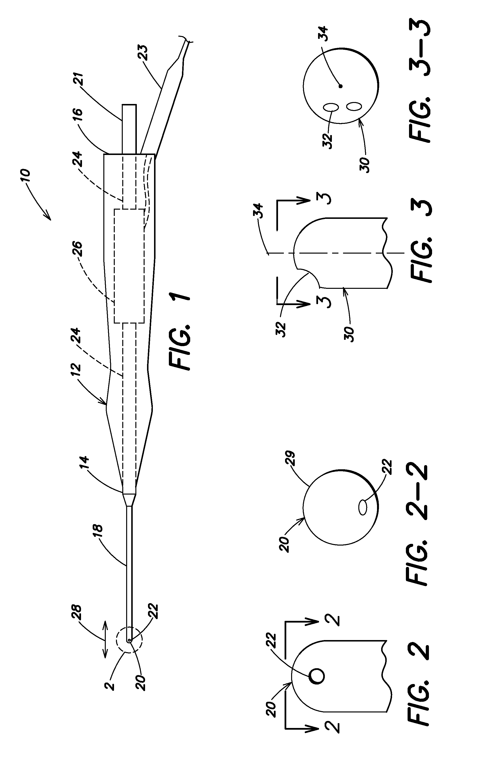
[0066]FIG. 1 is an elevation of an ophthalmic surgical device 10 according to one example embodiment. Device 10 includes a housing 12 having a distal end 14 and a proximal end 16. A cannula 18 is attached to the housing distal end 14. The cannula 18 has a distal tip 20 with at least one port 22 in communication with a lumen (not shown in FIG. 1) extending through the cannula 18 and in communication with an aspiration path 24 in the housing 12. A vibration source 26 is held within the housing 12 for vibrating the distal tip 20 of the cannula 18 for assisting in vitreous and other tissue removal from a patient's eye. An aspiration source (not shown in FIG. 1) is connected to aspiration path 24, via tube connector 21, for applying a negative pressure to the lumen and the at least one port 22 for removing fluids and the vitreous and other tissue from the eye. The vibration source 26 and the aspirat...


PUM


Abstract

An ophthalmic surgical device 10 includes a housing 12 having a distal end 14 and a proximal end 16. A cannula 18 is attached to the housing distal end 14 and has a distal tip 20 with at least one port 22 in communication with a lumen 19 extending through the cannula 18 and in communication with an aspiration path 24 in the housing 12. A vibration source 26 is held within the housing 12 for vibrating the distal tip 20 for assisting in vitreous and other tissue removal. An aspiration source 152 connected to the aspiration path 24 for applying a negative pressure to the lumen 19 and the at least one port 22 for removing fluids and the vitreous and other tissue from the eye. The vibration source 26 and the aspiration source 152 together create a periodic bi-directional flow of tissue through the port 22 without creating cavitation externally of the distal tip 20.

Description

BACKGROUND[0001]1. Field[0002]The present embodiment relates to an ophthalmic surgical device for the removal of vitreous and other tissue from a patient's eye and, more particularly, to an ophthalmic surgical device that vibrates a cannula with at least one port to disrupt and aspirate vitreous and other tissue from the eye.[0003]2. Description of the Related Art[0004]Vitrectomy cutters (or simply vit cutters) are ophthalmic medical device accessories indicated for use in removing the vitreous humour (often referred to within ophthalmology as “vitreous” or “vit”) from the posterior segment of the eye, which lies between the lens and the retina. Sometimes vitreous is removed because it is contaminated with materials that degrade vision (e.g., blood from ruptured vessels, or other cell material, referred to as vitreous floaters, that create spots in the visual field). Other times vitreous is removed to provide surgical access to structures on or near the retina. Also, vitreous is rem...

Claims


Application Information

Patent Timeline
Patent Type & Authority Applications(United States)
IPC IPC(8): A61F9/007
CPCA61F9/00745A61M1/84A61B17/320068
Inventor MCCARY, BRIAN D.GOH, TOH SENGPERKINS, JAMES TAYLOR
Owner BAUSCH & LOMB INC
Learn More