Eureka AIR delivers breakthrough ideas for toughest innovation challenges, trusted by R&D personnel around the world.

Internal cyclone for fluidized bed reactor

a fluidized bed reactor and internal cyclone technology, applied in the direction of furnaces, combustion types, uranium compounds, etc., can solve the problems of shutting down the whole fluidized bed reactor system, affecting the efficiency of the whole fluidized bed reactor, and the upflow of fluidizing gas, so as to achieve the effect of removing heavy cloggag

Inactive Publication Date: 2014-03-06
HONEYWELL INT INC
View PDF4 Cites 2 Cited by
  • Summary
  • Abstract
  • Description
  • Claims
  • Application Information

AI Technical Summary

Benefits of technology

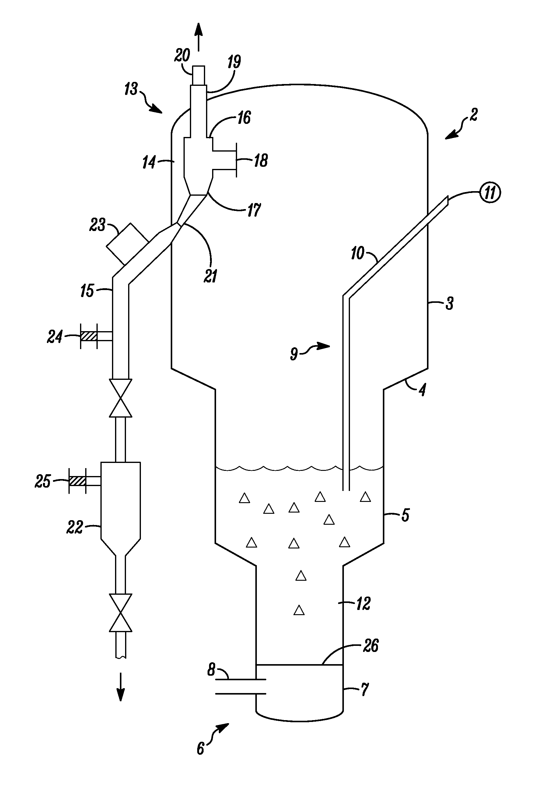
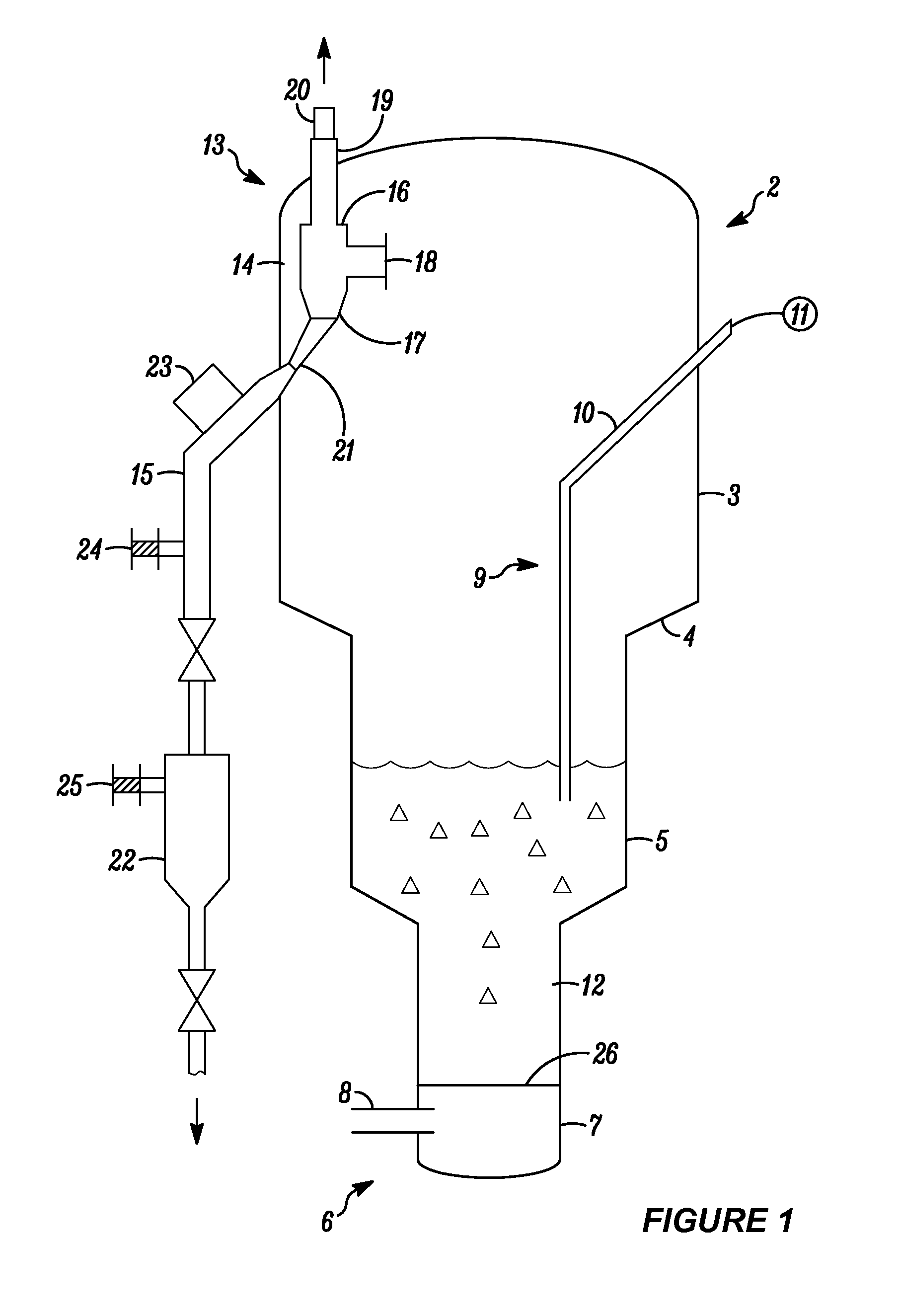
The present invention provides a fluidized bed reactor for the production of UF4 using a reaction column with a fluid portion, gas inflow means, particle feed means, and a cyclone capable of separating particles from the gas flowing upwardly from the fluid portion of the reaction column. The cyclone is located within the reaction column and is in communication with the gas flowing upwardly. The particle discharge pipe is located outside of the reaction column and can be connected to a knock-out pot or a high pressure N2 purge line for removing solids and heavy cloggage. The method of producing UF4 comprises reacting UO2 with HF gas in any of the fluidized bed reactors discussed above.

Problems solved by technology

Additionally, the inlet of the internal cyclone will not be easily clogged due to the high temperature of the process gas.
The drawback of this type of setup is that the up-flowing fluidizing gas may bypass the cyclone's inlet and enter the internal cyclone via its discharge pipe.
Another drawback is that the whole fluidized bed reactor system must be shut down in case the discharge pipe must be accessed and cleaned because it is clogged.
Additionally, the removal of captured fine particles from these types of systems is often difficult.

Method used


Image

  • Internal cyclone for fluidized bed reactor
  • Internal cyclone for fluidized bed reactor

Examples


Embodiment Construction

[0014]The invention relates to an improved fluidized bed reactor equipped with a cyclone that is located within the fluidized bed reactor's reaction column and that is connected to a particle discharge pipe located substantially outside of said reaction column. As a result of this modification, the fluidized bed reactor of the present invention operates more efficiently because the particle discharge pipe can be cleaned while the fluidized bed reactor is still in operation.

[0015]An embodiment of a fluidized bed reactor constructed in accordance with the present invention will now be described in detail with reference to the accompanying drawing (FIG. 1).

[0016]In FIG. 1, a fluidized bed reactor designated by numeral 1 operates according to the fluidized bed principles generally known in the art. The fluidized bed reactor has a reaction column 2, which extends substantially vertically, and which has a free board portion 3 of a relatively large-diameter cylindrical shape, a taper porti...


PUM


Abstract

A fluidized bed reactor comprising a reaction column having a fluid portion; a gas inflow means for flowing a gas upwardly from the fluid portion of the reaction column; a particle feed means for feeding particles to the fluid portion of the reaction column; a cyclone capable of separating particles from the gas flowing upwardly from the fluid portion of the reaction column, the cyclone being located within the reaction column and being in communication with the gas flowing upwardly, wherein the cyclone comprises a cyclone body having an inlet, a gas outlet, and a particle drop port; and a particle discharge pipe having an upper part connected to the particle drop port of the cyclone body, and a lower part, wherein the particle discharge pipe is located substantially outside of the reaction column.

Description

CROSS REFERENCE TO RELATED APPLICATION[0001]The present application claims priority under 35 U.S.C. §119(e) to U.S. Provisional Patent Application No. 61 / 695,179, filed on Aug. 30, 2012, the disclosure of which is incorporated herein by reference in its entirety.FIELD OF THE INVENTION[0002]This invention relates to an improved fluidized bed reactor equipped with an internal cyclone that is connected to a particle discharge pipe located substantially outside of the reaction column.BACKGROUND OF THE INVENTION[0003]A fluidized bed reactor (FBR) is a type of reactor device that can be used to carry out a variety of multiphase chemical reactions. In this type of reactor, a fluid (gas or liquid) is passed through a granular solid material (usually a catalyst possibly shaped as tiny spheres) at high enough velocities to suspend the solid and cause it to behave as though it were a fluid. This process, known as fluidization, imparts many important advantages to the fluidized bed reactor. The...

Claims


Application Information

Patent Timeline
IPC IPC(8): B01J8/24C01G43/06
CPCC01G43/06B01J8/24B01J8/1827B01J8/0055B01J2208/00681B01J2208/00752B01J2208/00761F23C10/08
Inventor YANG, TERRISJOHNSON, ROBERTTUNG, HSUEH SUNG
Owner HONEYWELL INT INC
Why Eureka
Eureka Blog
Learn More