
Fuel Assembly and Core of Nuclear Reactor

a nuclear reactor and fuel assembly technology, applied in nuclear engineering, nuclear elements, greenhouse gas reduction, etc., can solve the problem of monotonously decreasing reactivity of fuel assemblies without burnable poisons, and achieve the effect of further reducing the range of excess reactivity of the core during an operation cycl

Inactive Publication Date: 2014-03-06
HITACHI-GE NUCLEAR ENERGY LTD
View PDF2 Cites 5 Cited by
  • Summary
  • Abstract
  • Description
  • Claims
  • Application Information

AI Technical Summary

Benefits of technology

The present invention reduces the excess reactivity of the core during an operation cycle.

Problems solved by technology

The control rods and the burnable poison absorb neutrons excessively generated by the nuclear fission of nuclear fuel materials.
The fuel assemblies without the burnable poison have monotonously decreasing reactivity as its nuclear fuel material burns.

Method used


Image

  • Fuel Assembly and Core of Nuclear Reactor
  • Fuel Assembly and Core of Nuclear Reactor
  • Fuel Assembly and Core of Nuclear Reactor

Examples


embodiment 1

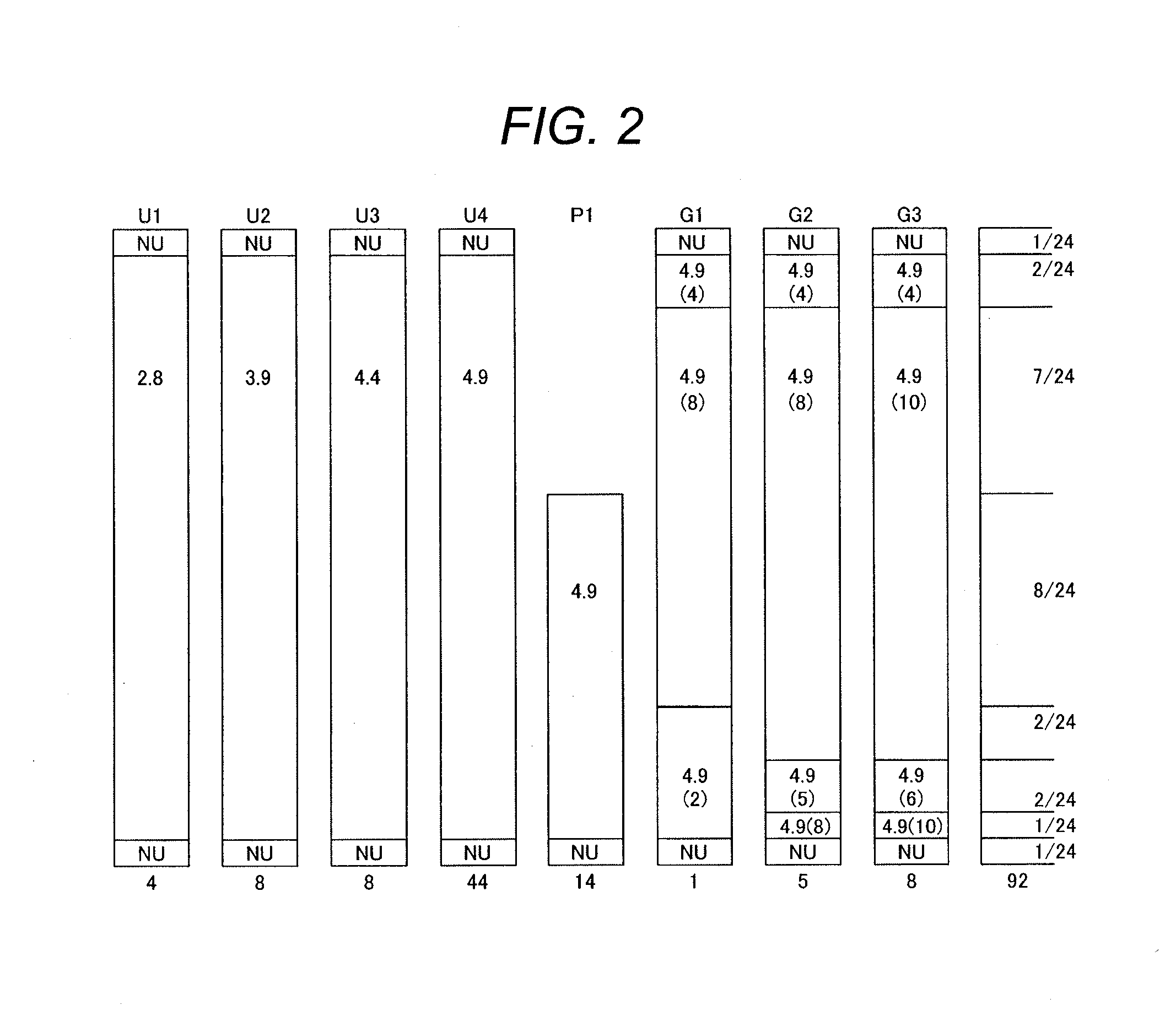
[0083]A fuel assembly according to embodiment 1, which is a preferred embodiment of the present invention, will be described with reference to FIGS. 1, 2, and 3. Fuel assemblies 1 with a burnup of 0 GWd / t according to the present embodiment are loaded into a core of a boiling water nuclear reactor.

[0084]The fuel assembly 1 according to the present embodiment is provided with a plurality of fuel rods 2, two water rods 5, a lower tie plate 6, an upper tie plate 7, a plurality of fuel spacers 8, and a channel box 9 as shown in FIG. 3. The fuel rod 2 is filled with a plurality of fuel pellets (not shown) formed with nuclear fuel material filled in a fuel cladding (not shown). A lower end portion of each fuel rod 2 is supported by the lower tie plate 6, and an upper end portion of each fuel rod 2 is supported by the upper tie plate 5. Part of the fuel rods 2 do not have a length from the lower tie plate 6 to the upper tie plate 5; these fuel rods are partial length fuel rods having a sho...

embodiment 2

[0114]A fuel assembly according to embodiment 2, which is another preferred embodiment of the present invention, will be described with reference to FIGS. 1 and 17. The fuel assembly according to the present embodiment (called fuel assembly 1A for convenience in writing to distinguish from the fuel assembly 1 according to embodiment 1) is for loading into the core of a boiling water reactor.

[0115]The fuel assembly 1A in the present embodiment is different from the fuel assembly 1 in embodiment 1 only in the distribution of gadolinia concentrations in the fuel rods G1, G2, and G3. The fuel rod G1 of the fuel assembly 1A, as shown in FIG. 17, is filled with the nuclear fuel material C containing 2 wt % gadolinia in a zone between the position up to 1 / 24 and a position up to 7 / 24 of the total axial length from the lower end of the active fuel length and the nuclear fuel material A containing 8 wt % gadolinia in a zone between the position up to 7 / 24 and the position up to 21 / 24 of the ...


PUM


Abstract

In a fuel assembly having fuel rods U1 to U4, and P1 not containing gadolinia, and fuel rods G1-G3 containing gadolinia, the concentrations a of gadolinia in nuclear fuel materials A (8 wt % and 10 wt %) satisfy 0.7<a / amax≦1.0, the concentrations b of gadolinia in nuclear fuel materials B (5 wt % and 6 wt %) satisfy 0.4<b / amax≦0.7, the concentration c of gadolinia in a nuclear fuel material C (2 wt %) satisfies 0<c / amax≦0.4, and L(A) / 5.0≧L(B) and L(B) / 5.0≧L(C) are satisfied. The gadolinia with concentrations a burns out during the end of cycle, the gadolinia with concentrations b during the middle of cycle, and the gadolinia with a concentration c during the beginning of cycle. L(A) is the total axial length of zones filled with the nuclear fuel materials A in the fuel rods G1-G3, L(B) for materials B in G2 and G3, and L(C) material C in G1.

Description

CLAIM OF PRIORITY[0001]The present application claims priority from Japanese Patent application serial no. 2012-191257, filed on Aug. 31, 2012, the content of which is hereby incorporated by reference into this application.BACKGROUND OF THE INVENTION[0002]1. Technical Field[0003]The present invention relates to a fuel assembly and a core of a nuclear reactor and, in particular, to a fuel assembly and a core of a nuclear reactor suitable for applying to a boiling water nuclear power plant.[0004]2. Background Art[0005]A plurality of fuel assemblies are loaded into a core in a reactor pressure vessel of a boiling water nuclear power plant. The fuel assembly has a plurality of fuel rods in which a plurality of fuel pellets containing nuclear fuel materials (for example, uranium dioxide) are disposed, a lower tie plate for supporting a lower end portion of each fuel rod, an upper tie plate for supporting a upper end portion of each fuel rod, a plurality of fuel spacers disposed in the ax...

Claims


Application Information

Patent Timeline
Patent Type & Authority Applications(United States)
IPC IPC(8): G21C3/328
CPCG21C3/328G21C3/3262Y02E30/30
Inventor NAKADOZONO, NAOYUKIMITSUYASU, TAKESHIIKEGAWA, TOMOHIKO
Owner HITACHI-GE NUCLEAR ENERGY LTD
Learn More