
Received signal gain control method and radio frequency signal receiving apparatus

Inactive Publication Date: 2009-06-04
SAMSUNG ELECTRONICS CO LTD
View PDF5 Cites 4 Cited by
  • Summary
  • Abstract
  • Description
  • Claims
  • Application Information

AI Technical Summary

Benefits of technology

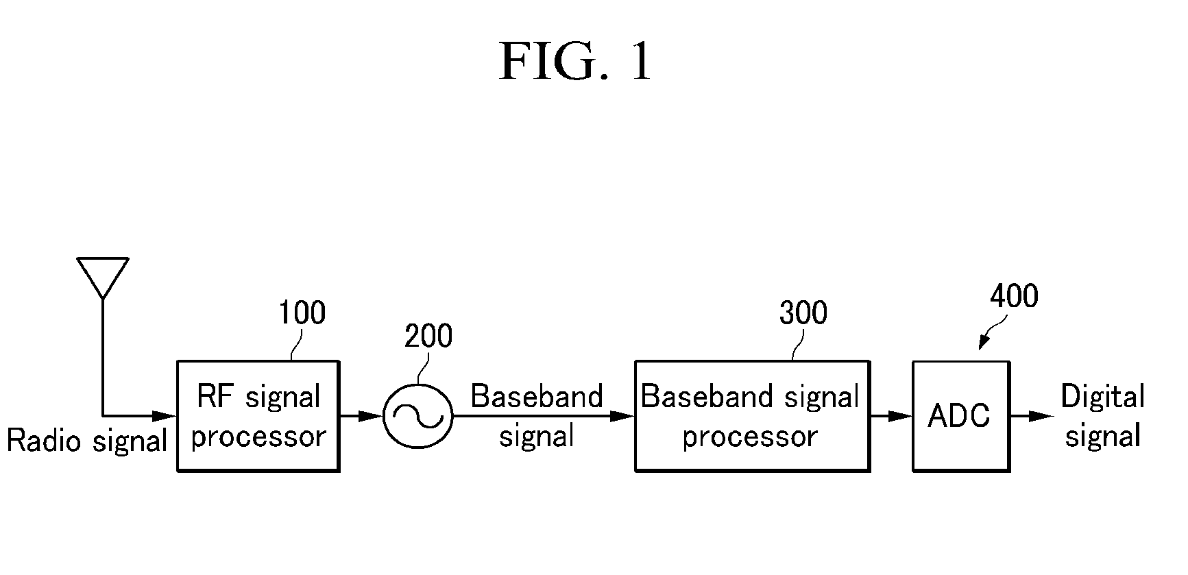
[0012]The present invention has been made in an effort to provide a radio signal receiving apparatus that can reduce noise and power consumption, and a received signal gain control method thereof.
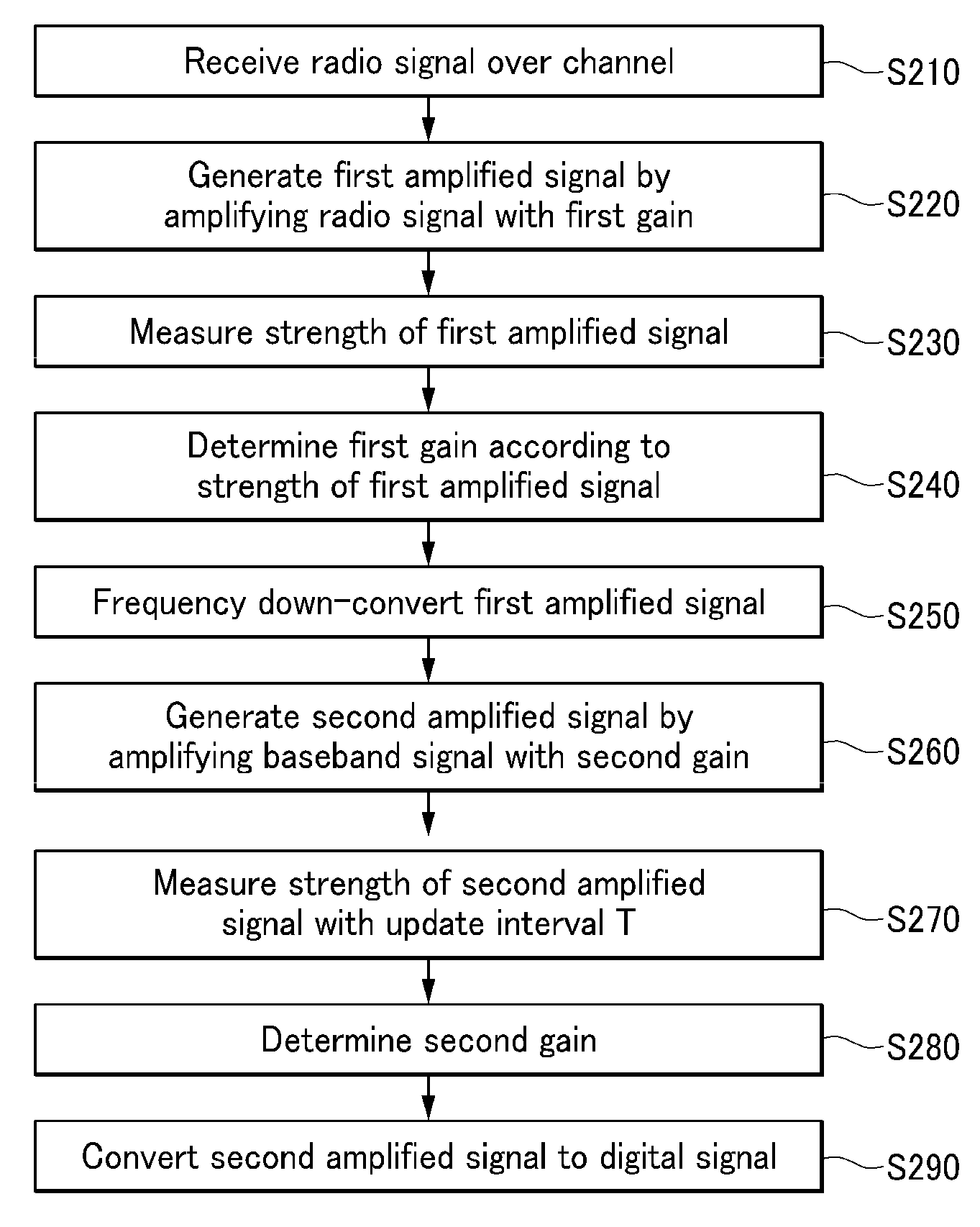
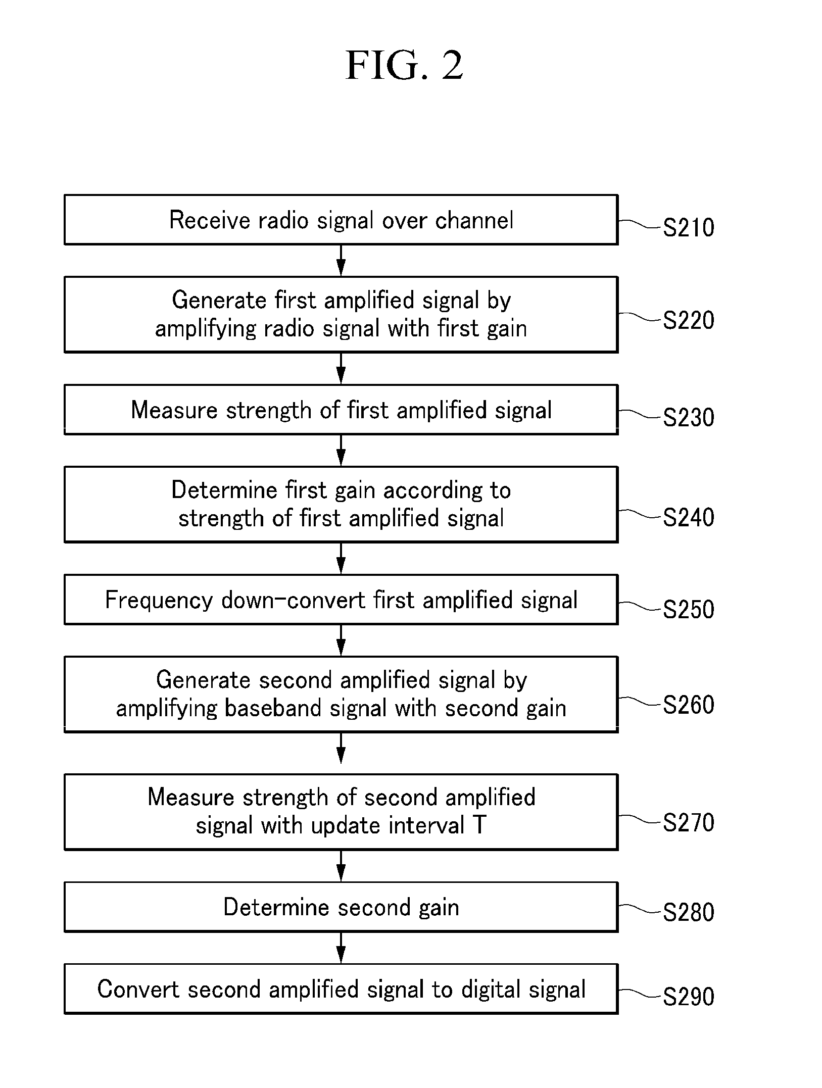
[0024]According to the present invention, low-noise amplification is gradually performed with a gain according to a strength of a received signal measured in the state of an RF signal and AGC amplification is performed with a gain according to the strength of the received signal measured in the state of a digital signal so that a variation range of the AGC amplification and noise can be reduced. In addition, a time interval for measuring the strength of the radio signal in the state of a digital signal can be variably set according to a variation rate of the strength measured in the state of a digital signal, and accordingly, unnecessary operation and control signal generation can be reduced, thereby reducing power consumption.

Problems solved by technology

As described, conversion from a digital voltage control signal to an analog voltage control signal causes occurrence of unexpected noise.
Such a persistent operation increases power consumption of the receiving apparatus.

Method used


Image

  • Received signal gain control method and radio frequency signal receiving apparatus
  • Received signal gain control method and radio frequency signal receiving apparatus
  • Received signal gain control method and radio frequency signal receiving apparatus

Examples


Embodiment Construction

[0030]In the following detailed description, only certain exemplary embodiments of the present invention have been shown and described, simply by way of illustration. As those skilled in the art would realize, the described embodiments may be modified in various different ways, all without departing from the spirit or scope of the present invention. Accordingly, the drawings and description are to be regarded as illustrative in nature and not restrictive. Like reference numerals designate like elements throughout the specification.

[0031]In addition, unless explicitly described to the contrary, the word “comprise” and variations such as “comprises” or “comprising” will be understood to imply the inclusion of stated elements but not the exclusion of any other elements. In addition, the terms “-er”, “-or”, and “module” described in the specification mean units for processing at least one function and operation and can be implemented by hardware components or software components and com...


PUM


Abstract

A radio signal receiving apparatus receiving a radio signal over a radio channel generates a first amplified signal by amplifying the radio signal with a first gain, and determines the first gain by measuring the strength of the first amplified signal. In addition, the radio signal receiving apparatus generates a down-converted signal by frequency down-converting the first amplified signal, and generates a second amplified signal by amplifying the down-converted signal with a second gain. In addition, the radio signal receiving apparatus determines the second gain by measuring the strength of the second amplified signal.

Description

CROSS-REFERENCE TO RELATED APPLICATION[0001]This application claims priority to and the benefit of Korean Patent Application No. 10-2007-0122749 filed in the Korean Intellectual Property Office on Nov. 29, 2007, the entire contents of which are incorporated herein by reference.BACKGROUND OF THE INVENTION[0002](a) Field of the Invention[0003]The present invention relates to a received signal gain control method and a radio signal receiving apparatus.[0004]This work was supported by the IT R&S program of MIC / IITA [2005-S-404-13, Research & Development of Radio Transmission Technology for 3G evolution].[0005](b) Description of the Related Art[0006]A typical receiving apparatus of a wireless communication system performs gain control by amplifying a received radio signal with a predetermined gain.[0007]The receiving apparatus frequency down-converts the received radio signal and converts the frequency down-converted radio signal to a digital signal, and measures the strength of the sign...

Claims


Application Information

Patent Timeline
IPC IPC(8): H03G3/20
CPCH03G3/3068H03D1/00H04B1/14H04W24/10
Inventor KANG, BYUNG SUKWON, HEON KOOKLEE, KWANG CHUN
Owner SAMSUNG ELECTRONICS CO LTD
Learn More