
Cathodic protection monitoring method, system and components

a monitoring method and cathode technology, applied in weather/light/corrosion resistance, instruments, reradiation, etc., can solve the problems of interrupting protection, high cost of conventional monitoring based on periodic site visits, and electrochemical corrosion of underground metal structures, etc., to achieve accurate assessment of cp systems and low cost

Inactive Publication Date: 2014-03-06
NEUMAN MICHAEL ALEXANDER ST LEGER +3
View PDF7 Cites 11 Cited by
  • Summary
  • Abstract
  • Description
  • Claims
  • Application Information

AI Technical Summary

Benefits of technology

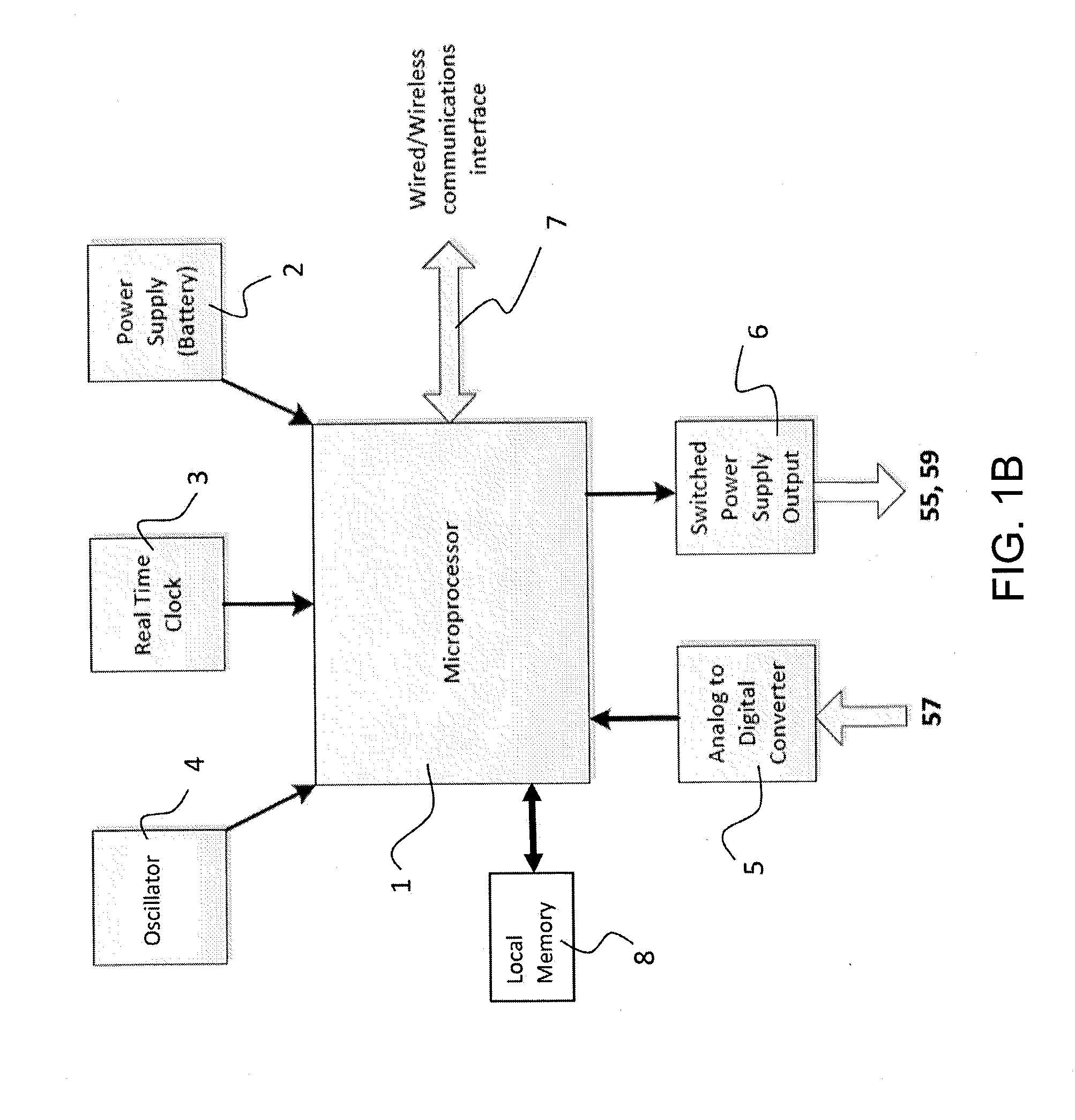
The present invention provides methods, systems and components for monitoring CP systems, particularly for protecting buried storage tanks. The methods allow for regular, daily or more frequent potential data collection, providing accurate assessment of CP systems. The monitoring is low cost and reliable, with the system components being durable and stable over a lifetime. Additionally, the invention includes an on-site integrated coupon / in situ reference electrode element and a potential measurement device, control unit, and communications interface for selectively scheduled potential difference measurements, averaging, and transmission of data to a remote database. This invention offers an improved method for protecting buried storage tanks from corrosion.

Problems solved by technology

Underground metal structures, particularly steel structures, including storage tanks, pipes and construction support members, are subject to electrochemical corrosion.
However, conventional monitoring based on periodic site visits is costly.
Conventional manual monitoring of cathodic protection systems normally requires disconnection of the anodes from the metal structure, interrupting protection.
Additionally, failure to reconnect the anodes after monitoring results in unintended loss of cathodic protection.

Method used


Image

  • Cathodic protection monitoring method, system and components
  • Cathodic protection monitoring method, system and components
  • Cathodic protection monitoring method, system and components

Examples


Embodiment Construction

[0030]The Invention is further described by reference to the drawings wherein the same numbers represent the same elements.

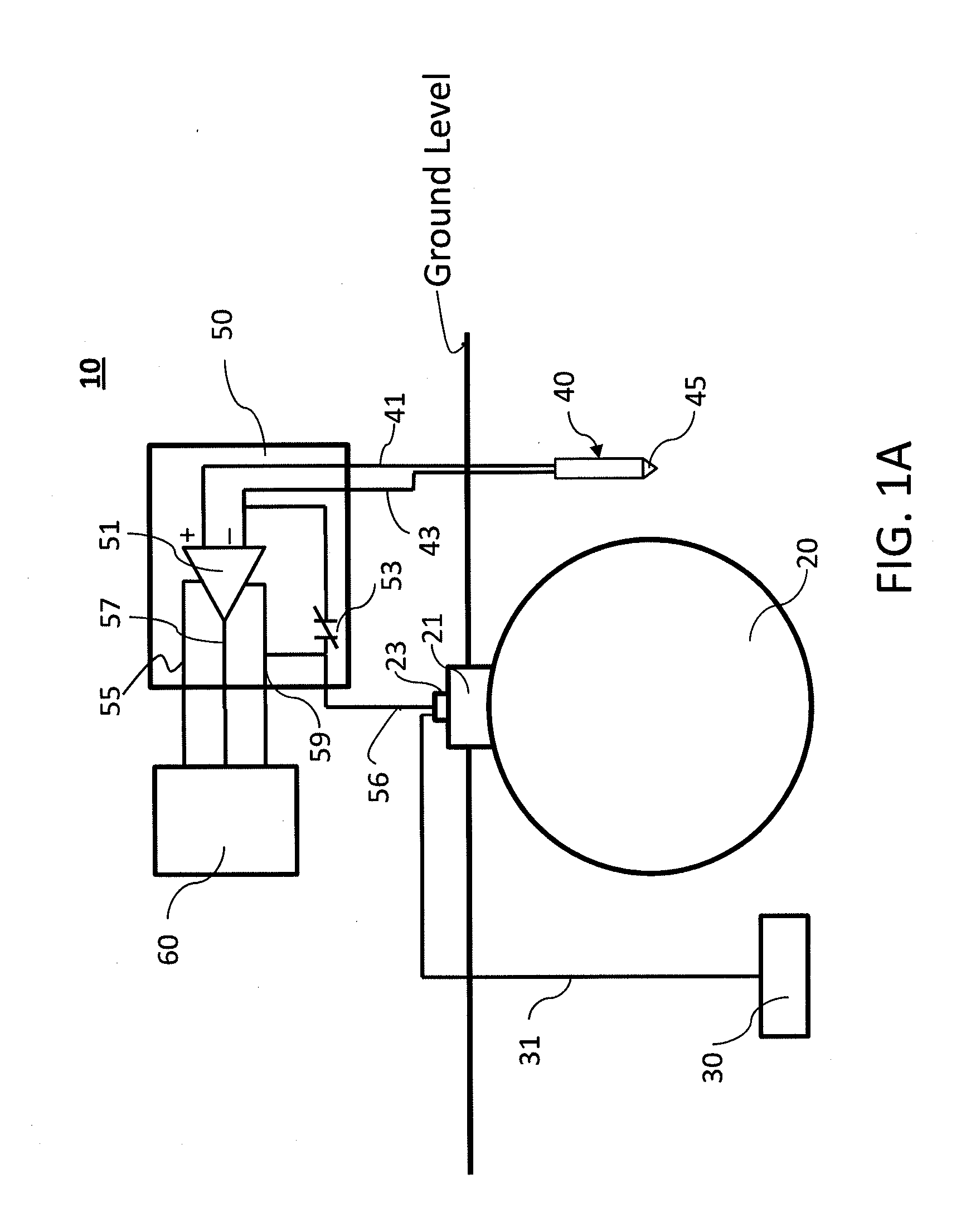
[0031]FIG. 1A illustrates on-site components of an exemplary cathodic protection monitoring system 10 of this invention. The system as illustrated is implemented wherein the structure to be protected is a metal underground storage tank 20 with turret 21 and bus bar 23 electrically connected (via insulated electrical cable 31) to a sacrificial anode 30. The monitoring system comprises stake 40, which carries a coupon 46, a reference electrode 47, and electrical cable for connection as described below; a potential measurement device 50; and a control unit 60 which provides for wired / wireless communication as discussed below.

[0032]The stake has driving tip 45 to facilitate driving the stake into the ground. The stake comprises a coupon 46 and a reference electrode 47 (illustrated in more detail in FIGS. 2-7) which are integrated into the stake and insulated from ea...


PUM


Abstract

Cathodic protection (CP) monitoring methods, systems and system components that provide regular (typically daily or more frequent) potential data collection for accurate assessment of CP systems. The methods, systems and components of the invention are used for remote monitoring of passive sacrificial anode CP systems and more particularly for monitoring of CP protection for buried storage tanks. These systems have on-site components for collection of data and transmission of data to remote databases and can employ computer-implemented and / or system operator assessed data processing and interpretation of data to assess protection status of a given structure and further to generate appropriate reports of protection status and collected and processed data.

Description

CROSS-REFERENCE TO RELATED APPLICATIONS[0001]This application claims the benefit of U.S. provisional application 61 / 621,282, filed Apr. 6, 2012, which application is incorporated by reference herein in its entirety.BACKGROUND OF THE INVENTION[0002]Underground metal structures, particularly steel structures, including storage tanks, pipes and construction support members, are subject to electrochemical corrosion. The soil in which the structures are buried is an electrolyte and the structures in contact with this electrolyte act as an electrode. In addition to the use of anti-corrosion coating, cathodic protection (CP) is often used to inhibit or prevent electrochemical corrosion.[0003]Cathodic protection systems function by connecting an anode to the metal structure to be protected and generating an electrical current such that the metal structure becomes a cathode and is protected from corrosion. CP systems include passive, sacrificial anode systems or active, impressed current sys...

Claims


Application Information

Patent Timeline
IPC IPC(8): G01V3/02
CPCG01V3/02C23F13/22G01N17/043
Inventor NEUMAN, MICHAEL ALEXANDER ST LEGERHADDY, JOHN RICHARDROBERTSON, DAVID EDWARDCOX, ROBERT LESLIE
Owner NEUMAN MICHAEL ALEXANDER ST LEGER
Learn More