
Cycle piston engine power system

a technology of power system and cycle piston engine, which is applied in the direction of machines/engines, energy input, separation processes, etc., can solve the problems of reducing specific power, reducing engine cycle efficiency, and being difficult to achieve, so as to reduce capital cost, improve efficiency, and achieve the effect of the same or better net cycle efficiency (specific fuel consumption)

Active Publication Date: 2014-03-06
ENHANCED ENERGY GRP
View PDF3 Cites 20 Cited by
  • Summary
  • Abstract
  • Description
  • Claims
  • Application Information

AI Technical Summary

Benefits of technology

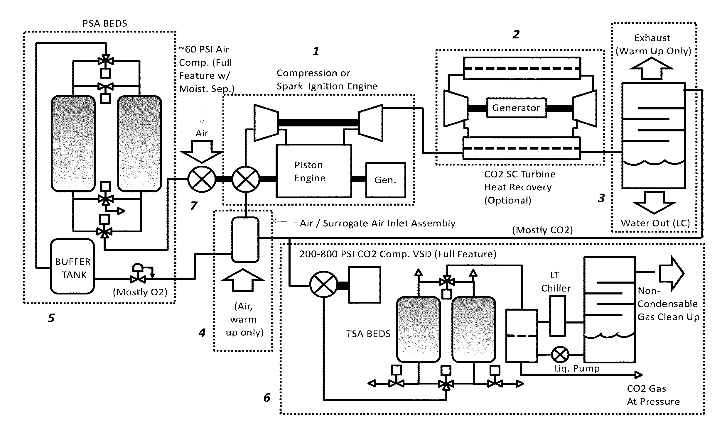
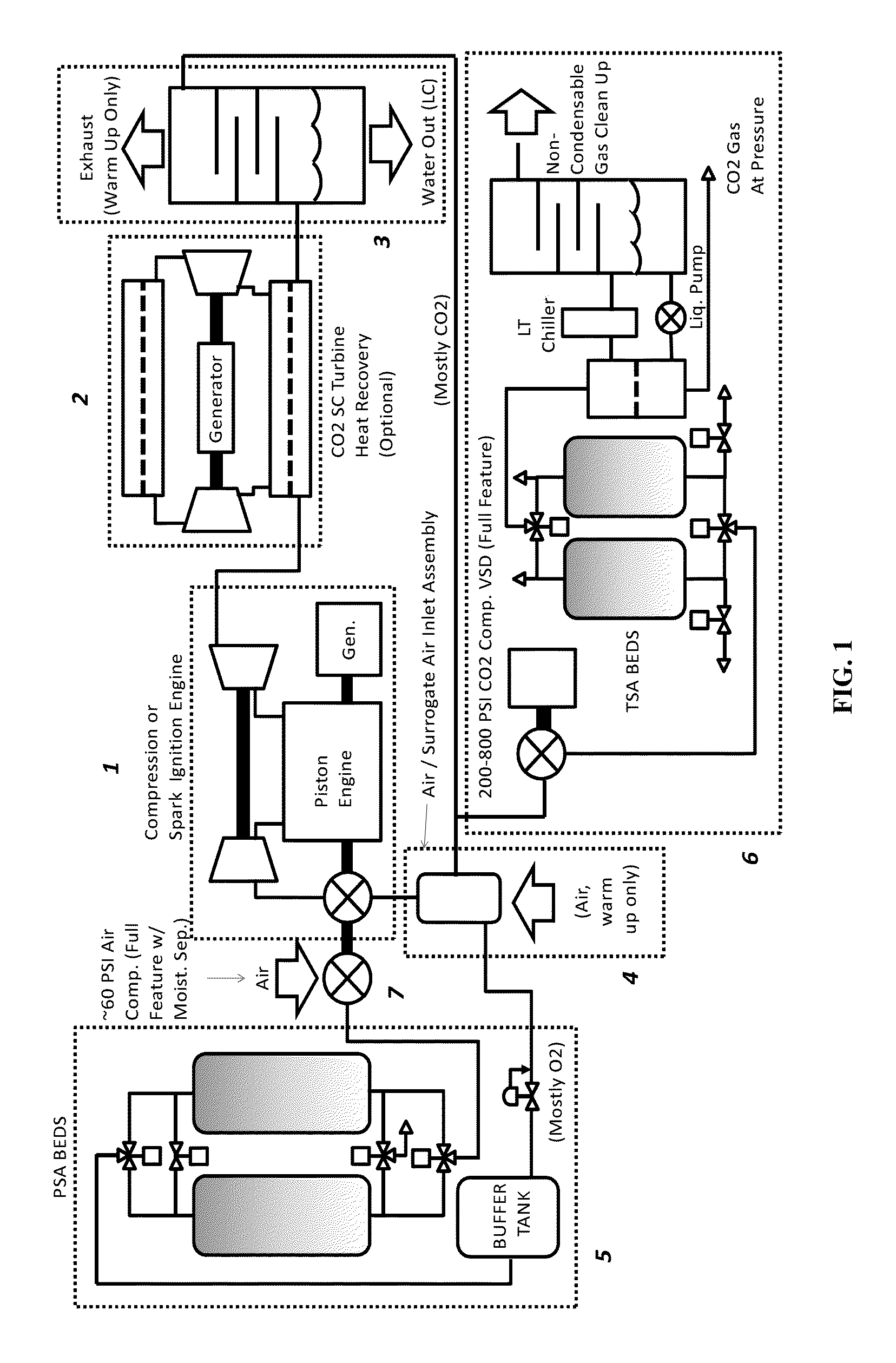
The invention is an improved piston engine power system that is compact, operates at high exhaust pressures and integrates engine operation, heat recovery, oxygen generation, and gas clean up to improve efficiency and lower costs. The system produces non-emissive power and also allows for the generation of saleable CO2 at pressure. Additionally, the system allows for independent control of excess oxygen and oxygen to diluent ratio, which allows for the use of low-heat value fuels or fuel water slurries while still achieving good combustion in the engine.

Problems solved by technology

Emissions of the untreated flue gas to the air, while simple to execute, is not desirable for environmental reasons.
In special purpose applications, in particular for undersea applications, the requirement to tie the system exhaust pressure to the ambient pressure (elevated backpressure) can lower engine cycle efficiency significantly.
In other special purpose applications, in particular at higher altitudes, the requirement to tie the system pressure to the ambient pressure (reduced inlet pressure) can reduce specific power significantly, and may also impact efficiency.
There are some technical problems with this patent, but it is intended to operate at depth and at high enough backpressure that both the CO2 and water product are condensed together as liquids, without the use of cryogenic oxygen.
Injector design for direct use of H2O2 is critical as decomposition can occur at points in the cycle where it would not be desirable.
However, U.S. Pat. No. 3,134,228, does not disclose any details or methodologies associated with product gas clean up.

Method used


Image

  • Cycle piston engine power system
  • Cycle piston engine power system
  • Cycle piston engine power system

Examples


Embodiment Construction

[0037]The present invention is now described more fully with reference to the accompanying drawings, in which an illustrated embodiment of the present invention is shown. The present invention is not limited in any way to the illustrated embodiment as the illustrated embodiment described below is merely exemplary of the invention, which can be embodied in various forms, as appreciated by one skilled in the art. Therefore, it is to be understood that any structural and functional details disclosed herein are not to be interpreted as limiting, but merely as a basis for the claims and as a representative for teaching one skilled in the art to variously employ the present invention. Furthermore, the terms and phrases used herein are not intended to be limiting but rather to provide an understandable description of the invention.

[0038]Where a range of values is provided, it is understood that each intervening value, to the tenth of the unit of the lower limit unless the context clearly d...


PUM


Abstract

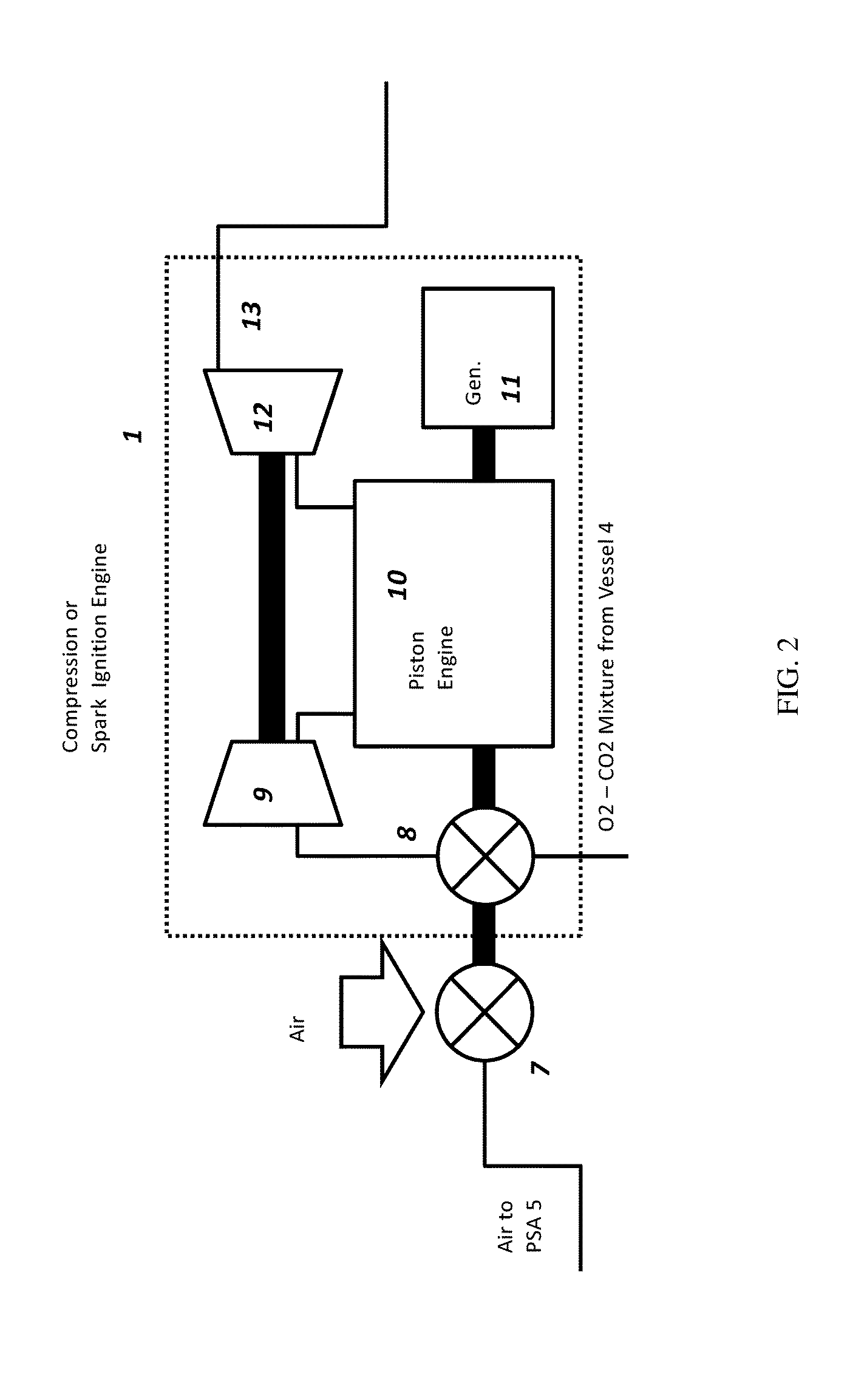
Disclosed is a cycle piston engine power system in which a compression ignition or spark ignition reciprocating piston engine is made non-emissive via a semi-closed cycle, in a manner which produces saleable CO2 product at pressure. The cycle piston engine power system can includes, among other elements, a piston engine for generating power and exhaust gas; a water cooling and separation unit which receives the exhaust gas and cools and removes water from the exhaust gas to create CO2 gas supply; a mixing pressure vessel which receives at least a portion of the CO2 gas supply from the water cooling and separation unit and mixes the CO2 gas supply with oxygen to create a working fluid to be provided to the piston engine; and an oxygen generator for providing oxygen to the mixing pressure vessel.

Description

CROSS REFERENCE TO RELATED APPLICATIONS[0001]This application claims priority to U.S. Provisional Patent Application Ser. No. 61 / 694,858, filed Aug. 30, 2012, entitled Cycle Piston Engine Power System, the disclosure of which is herein incorporated by reference in its entirety.BACKGROUND OF THE INVENTION[0002]1. Field of the Invention[0003]The invention generally relates to a cycle piston engine power system and more particularly to a semi-closed cycle piston engine power system having an integrated oxygen generation, SC CO2 heat recovery and carbon dioxide capture and clean-up sub-systems.[0004]2. Background of the Related Art[0005]Conventional power systems, whether internal or external combustion, burn fuel with air and generally vent the combustion products (exhaust / flue gas) to the air (or via underwater interface to the air). This is true of natural gas, gasoline, and diesel piston engines, and also of gas turbines, jet engines, or even steam boiler based power plants. Emissi...

Claims


Application Information

Patent Timeline
IPC IPC(8): F02M25/07
CPCF02M25/07Y02T10/12B01D53/0462F01N5/02F01K23/065F02B47/10F01N3/005F02M25/12F02B2075/025F01K23/068B01D53/047B01D53/22B01D53/261B01D53/265C01B13/0248B01D2256/12B01D2256/22B01D2257/102B01D2258/01C01B13/0251C01B13/0259F02M26/08F02M26/15F02M26/35F02M26/36Y02E20/18Y02P20/129Y02E20/34F01N2570/10
Inventor DUNN, PAUL M.
Owner ENHANCED ENERGY GRP
Learn More