Robust FM Modulation Detector Using Signal Autocorrelation

a detector and signal technology, applied in the field of frequency modulated radio communication, can solve the problems of difficult estimation of modulation, degrade performance, and contribute to additional noise, and achieve the effect of minimizing the effect of noise, and reducing the noise of the signal

Active Publication Date: 2014-02-27
TEXAS INSTR INC
View PDF0 Cites 0 Cited by
  • Summary
  • Abstract
  • Description
  • Claims
  • Application Information

AI Technical Summary

Benefits of technology

[0013]Modulation is calculated by measuring the autocorrelation of the recovered audio signal (the left channel and or the right channel), instead of its peaks, and then applying a peak hold detector. Since FM noise tends to be somewhat uncorrelated, this will result in a more accurate estimate of signal power while rejecting noise power substantially. Since the above measurement is similar to a power measurement, we compute its square root, adjust the gain to obtain a cleaner peak measurement, and then track these clean peaks using a leaky integrator. This gives an estimate of modulation while minimizing the effect of the noise.

Problems solved by technology

If the input filter's bandwidth is narrower than the required bandwidth, it will lead to distortion because necessary portions of the message spectrum have been clipped off.
However, if the RF signal level is weak, it will contribute to additional noise and thus degrade performance.
Estimation of modulation is a difficult problem.
The estimation is particularly hard when the RF signal level is weak, and when noise corrupts the signal.
However, under weak signal conditions, signal peaks get blanketed by noise peaks, so the peak-based approach overestimates the frequency deviation, thereby leading to a wider input filter than necessary and thus hurting SNR and SINAD.

Method used


Image

  • Robust FM Modulation Detector Using Signal Autocorrelation
  • Robust FM Modulation Detector Using Signal Autocorrelation
  • Robust FM Modulation Detector Using Signal Autocorrelation

Examples


Embodiment Construction

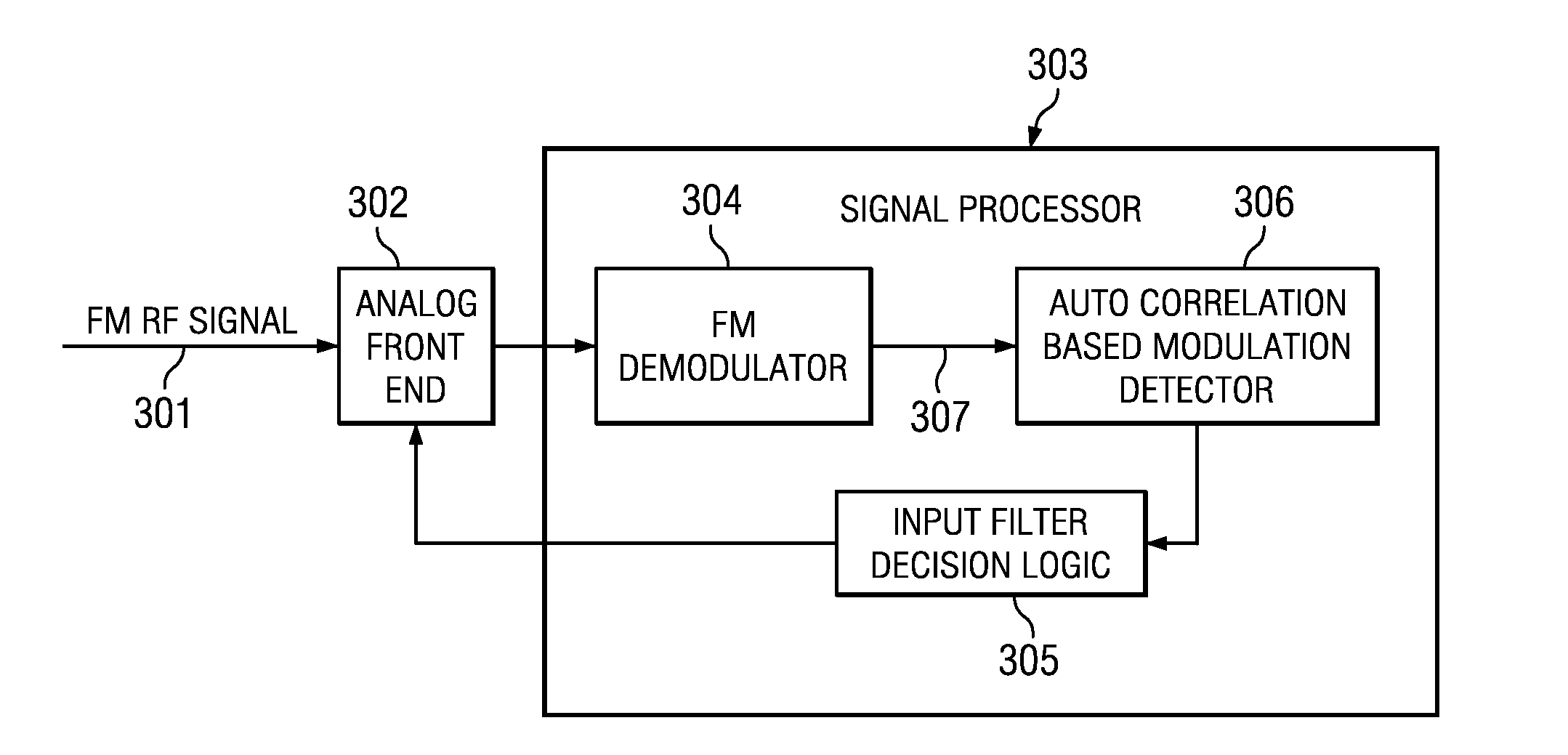
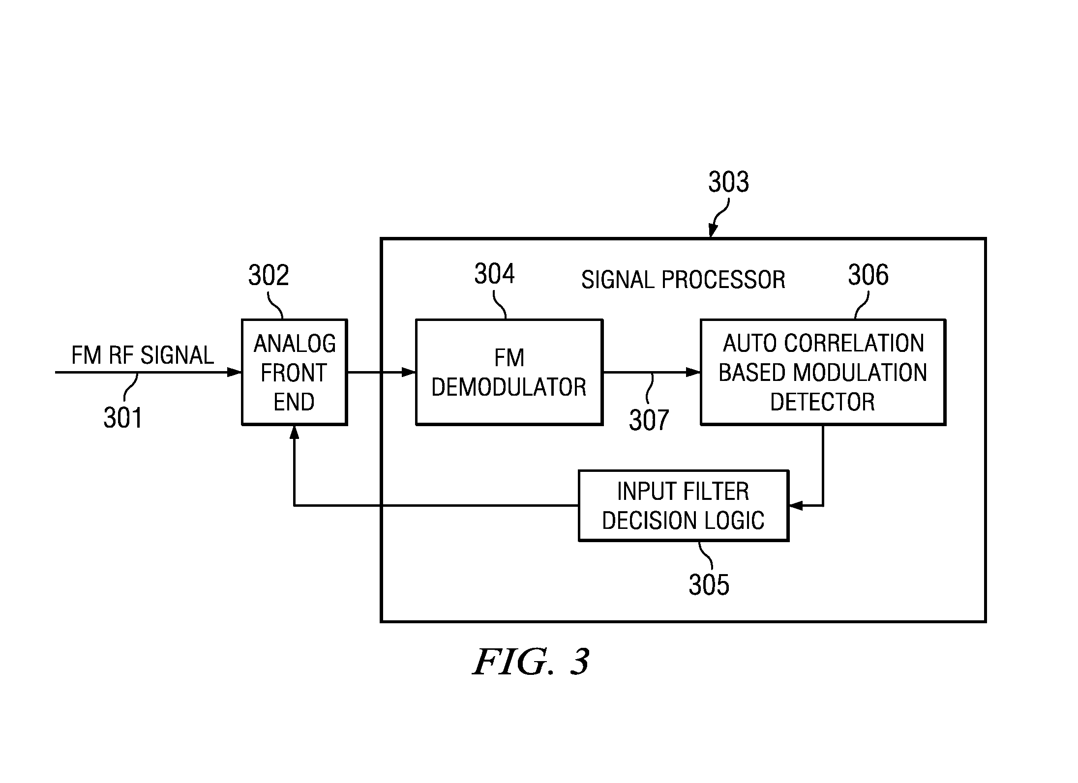
[0018]In the implementation shown in FIG. 3 the input to the system is the FM Radio Frequency (RF) signal 301, which feeds an Analog Front End (AFE) 302, that extracts the desired FM signal by filtering the appropriate portion of the frequency spectrum. The AFE also down converts the RF signal to a baseband signal, and performs Analog-to-Digital conversion. Thus, In phase—Quadrature phase (IQ) baseband samples are generated for the signal processor 303. The signal processor consists of an FM demodulator 304 implemented in software, where the output of the demodulator is the recovered audio signal. This is the input to the autocorrelation based modulation detector 306. The output of this block is the estimated modulation, which is used by the input filter decision logic 305 to convey the desired input filter to the AFE.

[0019]In the embodiment described the recovered audio signal 307 is the input to the autocorrelation calculation performed in block 306, as shown in the following equa...


PUM


Abstract

An FM receiver is unaware of the modulation level (frequency deviation) of the signal and has to make an estimate of it, or some reasonable time-average of it, and accordingly set the input filter's bandwidth. We calculate modulation by measuring the autocorrelation of the recovered audio signal instead of its peaks, and then applying a peakhold detector. Since FM noise can be modeled to be somewhat uncorrelated, we can expect to get an accurate estimate of signal power while rejecting noise power substantially if we measure a one-sample delayed autocorrelation estimate. Since the above measurement is alike a power measurement, we compute its square root, gain adjust it to obtain a cleaner peak measurement, and then track these clean peaks using a leaky integrator. This gives an estimate of modulation that subdues the effect of the noise.

Description

TECHNICAL FIELD OF THE INVENTION[0001]The technical field of this invention is frequency modulated radio communication.BACKGROUND OF THE INVENTION[0002]In electronics and telecommunications, modulation is the process of varying one or more properties of a high-frequency periodic waveform, called the carrier signal, with a modulating signal which typically contains information to be transmitted. The three key parameters of a periodic waveform are its amplitude, its phase and its frequency. Any of these properties can be modified in accordance with a low frequency signal to obtain the modulated signal. Typically a high-frequency sinusoid waveform is used as carrier signal, but a square wave pulse train may also be used.[0003]The purpose of modulation is to convey a message signal, for example a digital bit stream or an analog audio signal, inside another signal that can be physically transmitted. Modulation of a sine waveform is used to transform a baseband message signal into a passb...

Claims


Application Information

Patent Timeline
Patent Type & Authority Applications(United States)
IPC IPC(8): H04L25/02
CPCH04L25/022H04H40/72H03D3/00H04B1/1646H04L27/16H04H20/48
Inventor RAO, SIRA PARASURAMAWHITECAR, JOHN ELLIOTT
Owner TEXAS INSTR INC
Why Eureka
Try Eureka