Electroluminescent device using electroluminescent compound as luminescent material

a technology of electroluminescent compound and luminescent material, which is applied in the direction of platinum group organic compound, energy-saving lighting, sustainable buildings, etc., can solve the problems of large advantages in view of power efficiency (lm/w), and achieve the effects of reducing driving voltage, improving luminous efficiency, and prolonging operation li

Inactive Publication Date: 2014-02-27
ROHM & HAAS ELECTRONICS MATERIALS LLC
View PDF1 Cites 154 Cited by
  • Summary
  • Abstract
  • Description
  • Claims
  • Application Information

AI Technical Summary

Benefits of technology

[0114]As set forth above, an organic electroluminescent device using a specific dopant-host organic electroluminescent compound according to the present invention had better luminous efficiency and longer operation life at a lower driving voltage as compared with a device using the existing electroluminescent material. It is considered that a specific combination of dopant and host has a comparative proper level of energy to show excellent luminous efficiency and long operation life.BEST MODE
[0115]Hereinafter, the present invention is further described by taking representative compounds of the present invention as examples with respect to the organic electroluminescent compound according to the invention, a preparing method thereof, and electroluminescent properties of the devices, but those examples are provided only for illustration of the embodiments, not being intended to limit the scope of the invention.Preparation

Problems solved by technology

Recently, development of organic EL device having high efficiency and long life property is becoming the most urgent issue, and particularly, development of materials more excellent than the existing electroluminescent materials is urgent, considering EL characteristic levels required for medium-large sized OLED panels.
However, they may be deformed when subjected to a high-temperature depositing process under vacuum, due to a low glass transition temperature and inferior thermal stability thereof.
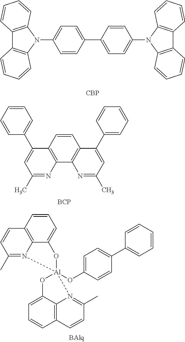
However, an OLED where the existing materials such as BAlq or CBP is used as a host of a phosphorescence electroluminescent material, has a higher driving voltage as compared with the OLED using a fluorescent material, and thus, large advantages are not present in view of power efficiency (lm / w).

Method used


Image

  • Electroluminescent device using electroluminescent compound as luminescent material
  • Electroluminescent device using electroluminescent compound as luminescent material
  • Electroluminescent device using electroluminescent compound as luminescent material

Examples


preparation example 2

Preparation of Compound 8

[0122]

Preparation of Compound 2-1

[0123]2,5-dibromopyridine 5 g (21 mmol) was treated in the same manner as the preparation method of Preparation Example 1 for Compound 1-1, thereby obtaining Compound 2-1 4 g (17 mmol).

Preparation of Compound 2-2

[0124]Compound 2-1 4 g (17 mmol), o-tolylboronic acid 2.8 g (20 mmol), and Pd(PPh3)41 g (0.9 mmol) were dissolved in toluene 80 mL, ethanol 40 mL, and 2M Na2CO3 40 mL in the presence of nitrogen, and then stirred under reflux at 120° C. Upon completion of the reaction after 2 hours, the resultant material was washed with distilled water, and extracted with ethyl acetate. The organic layer was dried over MgSO4 and the solvent was removed by a rotary evaporator, followed by purification using column chromatography, thereby obtaining Compound 2-2 (4 g, 15 mmol).

Preparation of Compound 2-3

[0125]2-Bromopyridine 5 g (21 mmol) was treated in the same manner as the preparation method of Preparation Example 1 for Compound 1-1,...

preparation example 3

Preparation of Compound 10

[0129]

Preparation of Compound 3-1

[0130]2.5-Dibromopyridine 5 g (21 mmol) was treated in the same manner as the preparation method of Preparation Example 1 for Compound 1-1, thereby obtaining Compound 3-1 2.6 g (11 mmol).

Preparation of Compound 3-2

[0131]Compound 3-1 2.6 g (11 mmol), d5-phenyl boronic acid 1.8 g (13 mmol), and Pd(PPh3)4 0.7 g (0.6 mmol) were dissolved in toluene 40 mL, ethanol 20 mL, and 2M Na2CO3 20 mL in the presence of nitrogen, and then stirred under reflux at 120° C. Upon completion of the reaction after 2 hours, the resultant material was washed with distilled water, and extracted with ethyl acetate. The organic layer was dried over MgSO4 and the solvent was removed by a rotary evaporator, followed by purification using column chromatography, thereby obtaining Compound 3-2 (2.2 g, 9.3 mmol).

Preparation of Compound 3-3

[0132]Compound 3-2 2.2 g (9.3 mmol), iridium chloride (IrCl3) 1.1 g (4.2 mmol), 2-ethoxyethanol 45 mL, and distilled wate...

preparation example 4

Preparation of Compound 20

[0136]

Preparation of Compound 4-1

[0137]2,5-Dibromo-4-methylpyridine 5 g (21 mmol) was treated in the same manner as the preparation method of Preparation Example 1 for Compound 1-1, thereby obtaining Compound 4-1 4 g (17 mmol).

Preparation of Compound 4-2

[0138]Compound 4-1 4 g (17 mmol), 4-fluorophenylboronic acid 2.8 g (20 mmol), and Pd(PPh3)41 g (0.9 mmol) were dissolved in toluene 80 mL, ethanol 40 mL, and 2M Na2CO3 40 mL in the presence of nitrogen, and then stirred under reflux at 120° C. Upon completion of the reaction after 2 hours, the resultant material was washed with distilled water, and extracted with ethyl acetate. The organic layer was dried over MgSO4 and the solvent was removed by a rotary evaporator, followed by purification using column chromatography, thereby obtaining Compound 4-2 (4 g, 15 mmol).

Preparation of Compound 4-3

[0139]Compound 4-2 4 g (15 mmol), iridium chloride (IrCl3) 2 g (6.8 mmol), 2-ethoxyethanol 90 mL, and distilled water ...


PUM

PropertyMeasurementUnit
electroluminescentaaaaaaaaaa
timeaaaaaaaaaa
Chemicalaaaaaaaaaa

Abstract

Provided is an organic electroluminescent device that exhibits an efficient host-dopant energy transfer mechanism, and thus, expresses a certain high-efficiency electroluminescent performance, based on improved electron density distribution. The organic electroluminescent device also overcomes low initial efficiency and short operation life property, and secures high-performance electroluminescent performance with high efficiency and long life property for each color.

Description

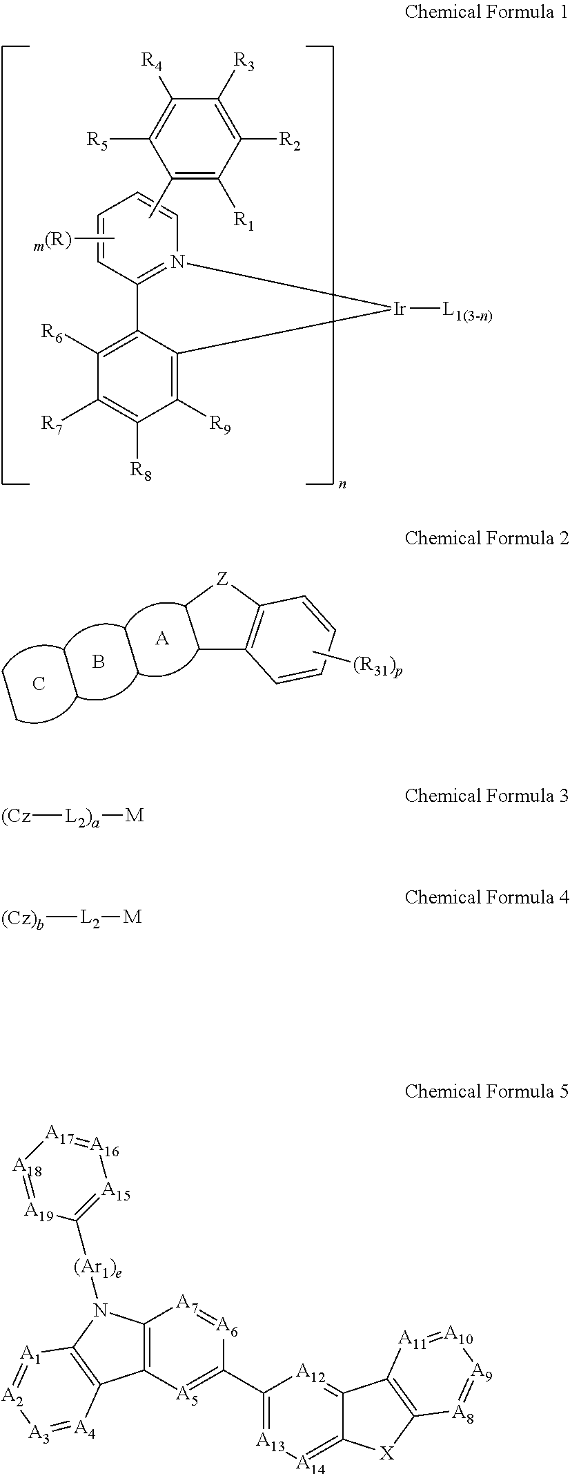
FIELD OF THE INVENTION[0001]The present invention relates to an organic electroluminescent device, and more particularly to an organic electroluminescent device where an organic layer is interposed between an anode and a cathode on a substrate, the organic layer including an electroluminescent layer containing one or more dopant compounds represented by Chemical Formula 1 below and one or more host compounds represented by Chemical Formulas 2 to 5 below.BACKGROUND OF THE INVENTION[0002]Among display devices, an electroluminescent device (EL device) is a self-luminescent display device, and has advantages of wider viewing angel as compared with LCD, excellent contrast, and fast response speed. An organic EL device, which uses aromatic diamine having a low molecular weight, and an aluminum complex, as a material for forming an electroluminescent layer, was first developed by Eastman Kodak Company in 1987 [Appl. Phys. Lett. 51, 913, 1987].[0003]In the organic EL device, when charges ar...

Claims


Application Information

Patent Timeline
Patent Type & Authority Applications(United States)
IPC IPC(8): H01L51/00
CPCH01L51/0067H01L51/0085H01L51/0074H01L51/0072H01L51/0094H01L51/0071C07B59/00C07D209/82C07D403/10C07D409/04C07D471/04C07D491/04C07D405/14C07D403/04C07D403/14C07D487/04C07D495/04C07F15/0033C09K11/06H05B33/14C09K2211/1007C09K2211/1029C09K2211/1033C09K2211/1037C09K2211/1044C09K2211/1059C09K2211/1088C09K2211/1092C09K2211/185C09B17/00C09B21/00C09B57/00C09B57/10C09B69/008Y02B20/00H10K85/622H10K85/30H10K85/654H10K85/6576H10K85/657H10K85/40H10K85/342H10K85/6572H10K50/11H10K2101/10H10K2102/103
Inventor KIM, CHI-SIKLEE, SOO-YOUNGKIM, YOUNG-GILLEE, HYO-JUNGLEE, SU-HYUNKIM, HYUNCHO, YOUNG-JUNKWON, HYUCK-JOOLEE, KYUNG-JOOKIM, BONG-OKKIM, SUNG-MIN
Owner ROHM & HAAS ELECTRONICS MATERIALS LLC
Why Eureka
Try Eureka