
Vibration and Pressure Damping Device for Gripping Handles and Steering Mechanisms

a technology of vibration damping and steering mechanism, which is applied in the direction of steering device, portable power-driven tools, cycle equipment, etc., can solve the problems of reducing the user's ability to control or control the vibrating object, affecting the operator's ability to control and maneuver the handgrip, and prone to injury of the nerve, so as to sufficiently attenuate the range of vibration and impact pressure. , the effect of reducing the range of vibration and impact pressur

Inactive Publication Date: 2014-02-27
FEINSTEIN PATENTS
View PDF21 Cites 17 Cited by
  • Summary
  • Abstract
  • Description
  • Claims
  • Application Information

AI Technical Summary

Benefits of technology

The present invention provides a damping device for a handgrip of a vibrating object that can attenuate vibrations and impact pressure exerted on the upper extremities of an operator. The device includes a bladder, an inflation device, and a controller that automatically adjusts the cushion pressure of the bladder by inflating or deflating it with a fluid to attenuate the vibrations and impacts transmitted through the handgrip. The device helps reduce fatigue in the upper extremities and also mitigates various impingement injuries in the upper extremities. Additionally, the device provides a comfortable grip with a uniform feel and consistent firmness, and it allows for fluid to flow freely between the bladder compartments.

Problems solved by technology

As a result, these nerves are prone to injury.
However, this apparatus does not provide a secure means for the grip to remain in stationary contact with the handle of the vibrating object.
Specifically, the air cushion grip can rotatably move about the handle while it is grasped by a hand, and thereby diminishes the user's ability to maneuver or control the vibrating object.
Further still, the air-cushion grip lacks the capability to adjust, in real-time, the damping levels of the air cells in order to accommodate the different vibrations and / or shocks that the object and its handle experience.
The covering does not integrate an inflation device to expand or contract the inflation cells.
Also, the covering is not adapted to provide real-time, continuous adjustments of the damping level provided by the covering.
Vibrations and impacts can vary in their frequency and amplitude, and as such, a single pressure damping level may not be sufficient in protecting a user's fingers, hands, wrists, arms, elbows and shoulders (herein “upper extremities”).
However, the arrangement does not include an integrated gas inflation device or a control unit to adjust damping levels of the chamber based on vibration characteristics (e.g., frequency, amplitude) and the strength of the user's grip (i.e., the amount of pressure applied to the chamber when the user is gripping the chamber).
Accordingly, the damping arrangement does not allow for independent configuration of the chambers and fails to provide localized damping, wherein different sections of the handlebar are provided different levels of vibration damping.
Moreover, Andersson is not adapted to provide for real-time adjustments of the damping levels of the air-tight chamber.
Further, the grip does not include an inflation device to adjust the volume of gas contained in the compartments.
As such, the pressure levels of the compartments remain constant and therefore are not adapted to provide varying damping effects.
The grip can rotate about the handlebar while the hands are grasping the grip, which reduces the user's ability to control the vibrating object.
While the prior art damping devices attached on the outer surfaces of handlebars of vibrating objects provide some vibration attenuating benefits compared to the handlebars alone, they still suffer from several disadvantages.
One such disadvantage is that these “exterior” damping devices may not remain rotatably stationary while mounted to the handlebars, and thus, may affect a person's ability to maneuver the vibrating object.
Further, the damping devices, when properly filled with gas, may substantially increase the overall size (i.e., perimeter) of the handlebar.
This makes gripping the handlebar, and in turn controlling the vibrating object, difficult.
Another disadvantage of the prior art damping devices is that they fail to provide continuous, real-time adjustments of damping levels or cushion pressure to sufficiently protect the upper extremities from different forms of vibration.
As such, the prior art damping devices provide limited vibration damping benefits at the expense of adequate control over the vibrating object.

Method used


Image

  • Vibration and Pressure Damping Device for Gripping Handles and Steering Mechanisms
  • Vibration and Pressure Damping Device for Gripping Handles and Steering Mechanisms
  • Vibration and Pressure Damping Device for Gripping Handles and Steering Mechanisms

Examples


Embodiment Construction

[0038]The following detailed description illustrates the invention by way of example, not by way of limitation of the principles of the invention. This description will enable one skilled in the art to make and use the invention, and describes several embodiments, adaptations, variations, alternatives and uses of the invention, including what is presently believed to be the best mode of carrying out the invention.

[0039]As used herein, the terms “upper extremity” and “upper extremities” encompasses the fingers, hands, wrists, arms, elbows and shoulders of a person.

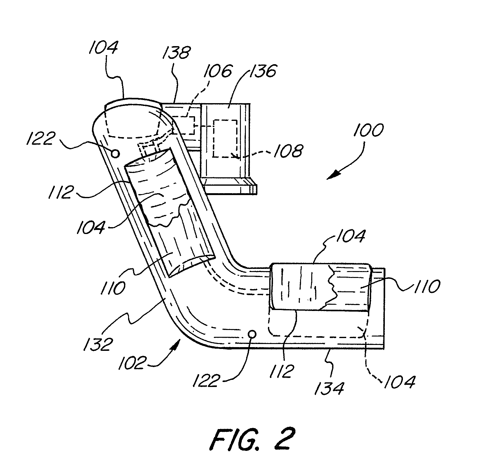
[0040]Referring to the figures in detail and first to FIGS. 1-3, there is shown an exemplary embodiment of a damping device for protecting the upper extremities of a person (“operator”) who is operating a vibrating object against vibrations, impact pressure, and shocks transmitted through the handgrip. The damping device 100 shown in FIG. 1 is implemented into the handgrip 102 of a bicycle. Although this figure and the foll...


PUM


Abstract

A damping device for a handgrip of an object includes a bladder disposed in said handgrip, an inflation device in fluid communication with the bladder, and a controller adapted to detect at least one of vibrations and impact pressure, and automatically adjust a cushion pressure of said bladder by causing the inflation device to inflate or deflate the bladder with a fluid as appropriate in order to attenuate the at least one of vibrations and impact pressure transmitted through said handgrip.

Description

FIELD OF THE INVENTION[0001]This invention relates to vibration damping devices and more specifically, to an apparatus that dampens vibrations and pressure transmitted through gripping handles and steering mechanisms to a person's fingers, hands, wrists, elbows, arms and shoulders.BACKGROUND OF THE INVENTION[0002]The ulnar and median nerves—two of the three major nerves in the arm—are largely unprotected by muscles or bone. As a result, these nerves are prone to injury. Biker's Palsy, also known as Cyclist's Palsy and Handlebar Palsy, and Carpal Tunnel Syndrome (CTS) are two types of injuries caused by the compression of the ulnar and median nerves in the wrists. Both injuries are prevalent among cyclists and bikers because of the repetitive motion, vibration, and pressure exerted on their wrist joints for extended periods of time. However, these nerve injuries are also common in individuals who regularly grip or expose their hands to vibrating or impacting objects, such as steering...

Claims


Application Information

Patent Timeline
IPC IPC(8): B25G1/01
CPCB25G1/01B25F5/006B25D17/043B25D2250/195B25D2250/375B62K21/26B62K21/12B62K11/14
Inventor FEINSTEIN, PETER A.
Owner FEINSTEIN PATENTS
Learn More