
System and Method of Determining Timing Triggers for Detecting Gamma Events for Nuclear Imaging

a technology of timing triggers and nuclear imaging, applied in the field of nuclear medical imaging systems, can solve the problems of detector dead time, false triggers, detector limits, etc., and achieve the effect of reducing detector dead tim

Active Publication Date: 2014-02-20
SIEMENS MEDICAL SOLUTIONS USA INC +1
View PDF9 Cites 18 Cited by
  • Summary
  • Abstract
  • Description
  • Claims
  • Application Information

AI Technical Summary

Benefits of technology

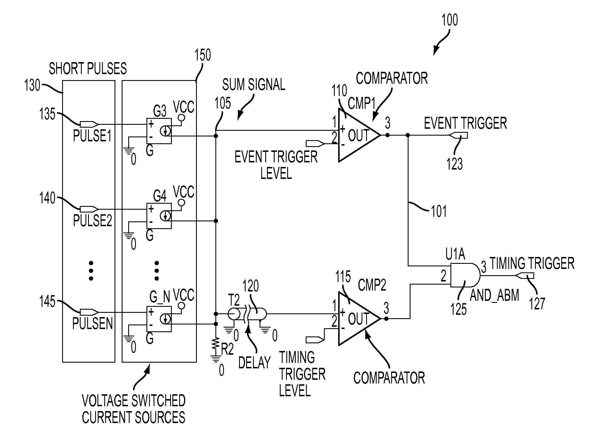
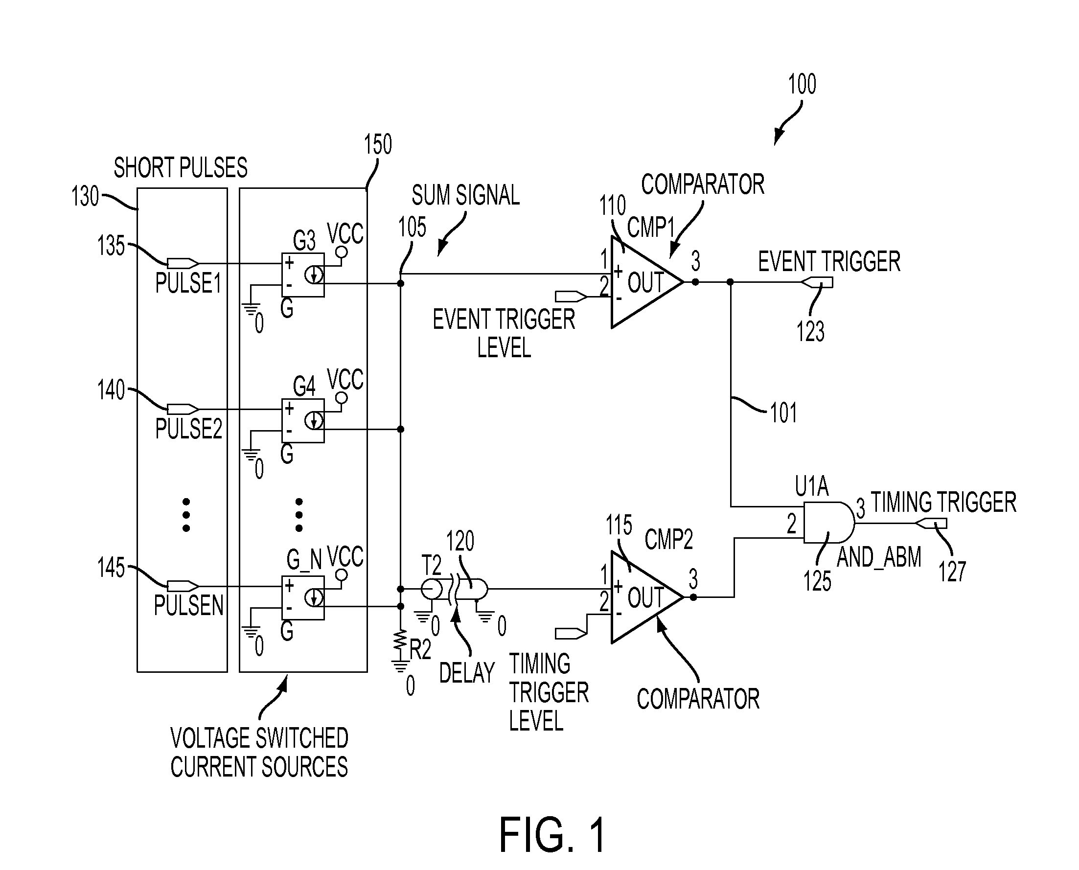
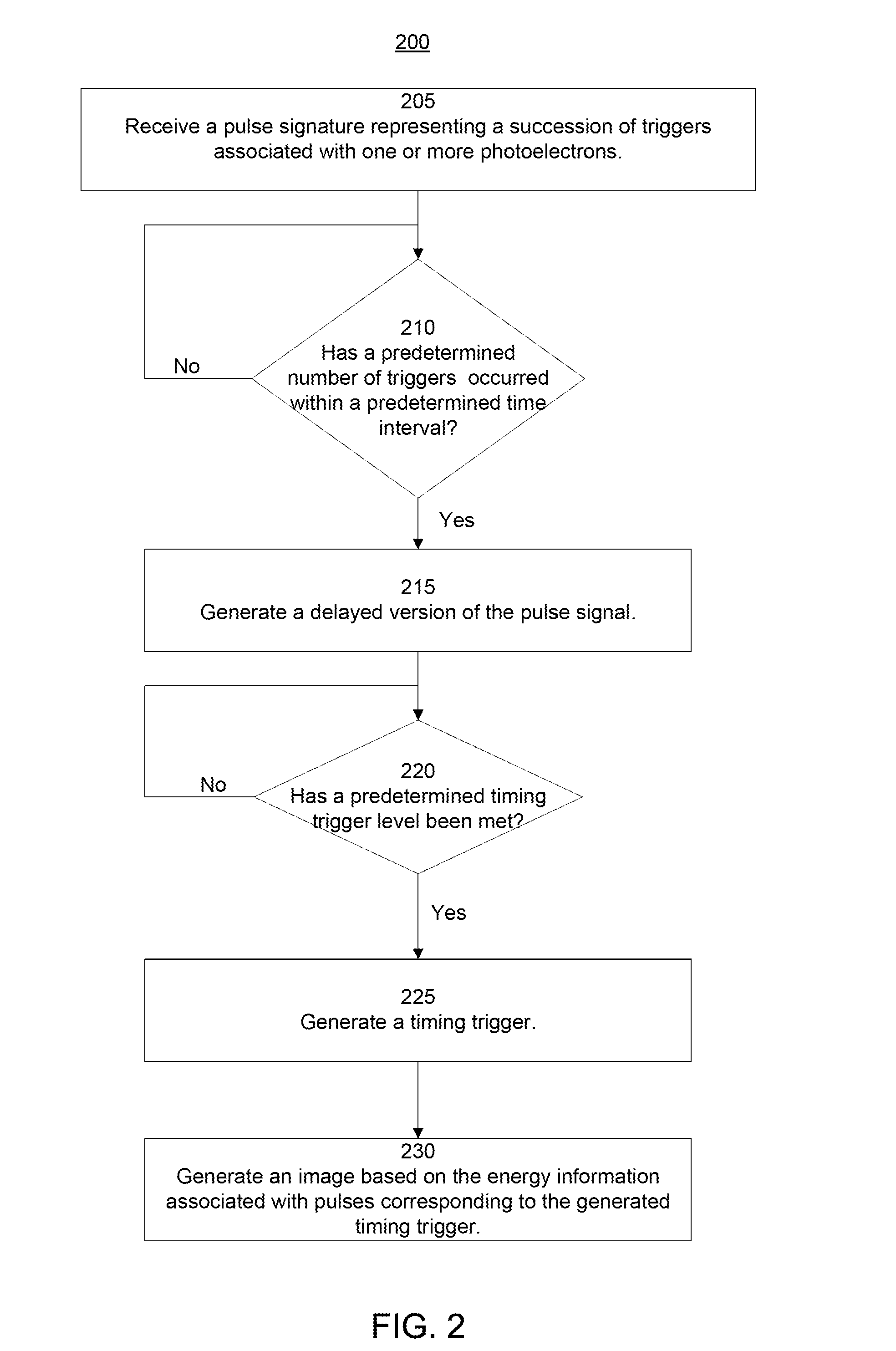
This patent is about a system and method for detecting gamma events in nuclear imaging. It reduces detector dead time and can identify true gamma events even in the presence of dark events and noise sources. The system uses a photomultiplier sensor and a timing trigger to determine when a gamma event occurs. The timing trigger is determined when a predetermined number of triggers occur within a predetermined time interval. This helps to account for and remove dark events and noise from consideration. The system also uses a delayed version of the pulse signature to compare with the predetermined trigger level and identify the front of the gamma event. The system then generates a timing trigger for data acquisition and utilizes the acquired information to generate a nuclear image.

Problems solved by technology

However, there are limits to how low the trigger level can be set due to the presence of random dark events of the SiPM microcells and other noise sources.
If the trigger level is too low, the dark rate noise can lead to a false trigger.
However, such verification schemes typically lead to detector dead time (that is, the time required for the sensor to perform the verification and for the data acquisition to be ready for the next event).
However, this has the drawback that any random dark pulse will also trigger the acquisition.
Thus, conventional photomultiplier sensors and schemes for acquiring data from the conventional photomultiplier sensors suffer from false triggers due to dark events and noise and detector dead time resulting from accounting for such false triggers.

Method used


Image

  • System and Method of Determining Timing Triggers for Detecting Gamma Events for Nuclear Imaging
  • System and Method of Determining Timing Triggers for Detecting Gamma Events for Nuclear Imaging
  • System and Method of Determining Timing Triggers for Detecting Gamma Events for Nuclear Imaging

Examples


Embodiment Construction

[0018]As required, disclosures herein provide detailed embodiments of the present disclosure; however, the disclosed embodiments are merely examples of the disclosure that may be embodied in various and alternative forms. Therefore, there is no intent that specific structural and functional details should be limiting, but rather the intention is that they provide a basis for the claims and as a representative basis for teaching one skilled in the art to variously employ the present disclosure.

[0019]As discussed above, conventional methods for determining timing trigger resolutions of gamma events of detectors such as SiPMs suffer from dark events such as false gamma events due to noise and dark pulses. Conventional methods of determining timing resolutions further suffer from dead time that is needed for a detector to verify that the detected gamma event is a true gamma event or that is needed for the detector to be ready to acquire data corresponding to the next gamma event. The pr...


PUM


Abstract

Systems and methods of generating timing triggers to determine timing resolutions of gamma events for nuclear imaging includes receiving a pulse signature representing a succession of triggers associated with a photomultiplier. When a number of triggers occurring within a predetermined time interval matches a predetermined number, an event trigger can be initiated. A delayed version of the pulse signature can be generated and compared to a predetermined timing trigger level. When the delayed version matches the predetermined timing trigger level, a timing trigger can be generated. Based on the timing trigger level, the timing trigger can be generated at the pulse of the delayed version that corresponds to the first photoelectron of a gamma event. The timing trigger can correspond to a timestamp for the first photoelectron so that a data acquisition system can identify the pulse from which to acquire energy information to generate a nuclear image.

Description

TECHNICAL FIELD[0001]The present disclosure relates to the field of nuclear medical imaging systems. Particularly, the present disclosure relates to systems and methods of determining timing triggers for detecting gamma events for nuclear imaging.BACKGROUND[0002]Medical imaging is one of the most useful diagnostic tools available in modern medicine. There are medical imaging processes of many types and for many different purposes, situations, or uses. They commonly share the ability to create an image of a bodily region of a patient, and can do so non-invasively. Examples of some common medical imaging types are nuclear medical (NM) imaging such as positron emission tomography (PET) and single photon emission computed tomography (SPECT), electron-beam X-ray computed tomography (CT), magnetic resonance imaging (MRI), and ultrasound (US). Using these or other imaging types and associated machines, an image or series of images may be captured. Other devices may then be used to process ...

Claims


Application Information

Patent Timeline
IPC IPC(8): G01T1/164H03K3/00
CPCG01T1/248G01T1/2985H03K3/033G01T1/164
Inventor HENSELER, DEBORAHANSEN, PETERSCHIENLE, MEINRAD
Owner SIEMENS MEDICAL SOLUTIONS USA INC
Learn More