
Method Of Minimizing Wellbore Instability

a wellbore instability and wellbore technology, applied in the field of minimizing wellbore instability, can solve the problems of inability to meet the needs of drilling fluid engineers, inability to perform geomechanical software as part of their duties, and inability to achieve the effect of reducing wellbore instability

Active Publication Date: 2014-01-30
MI
View PDF8 Cites 8 Cited by
  • Summary
  • Abstract
  • Description
  • Claims
  • Application Information

AI Technical Summary

Benefits of technology

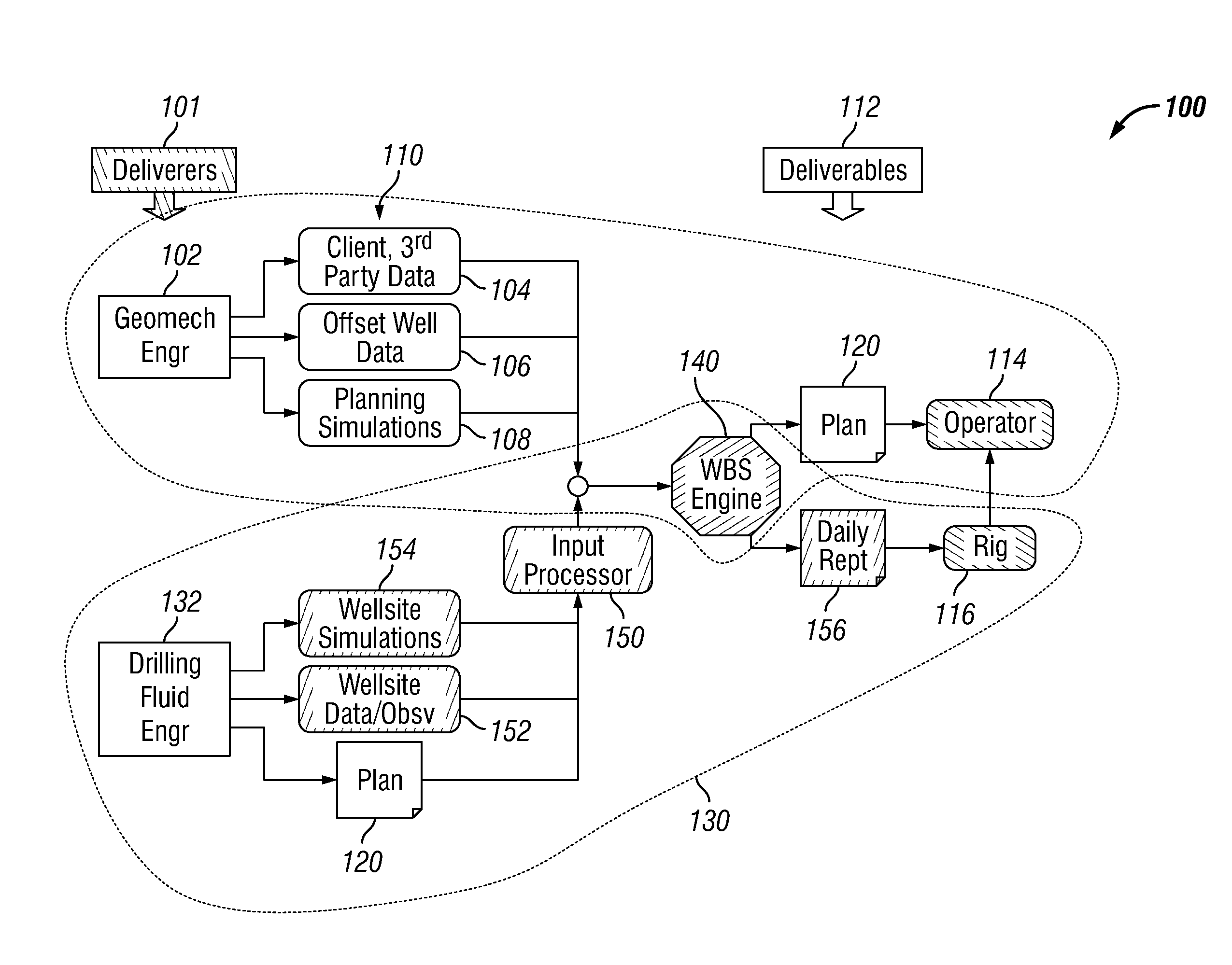
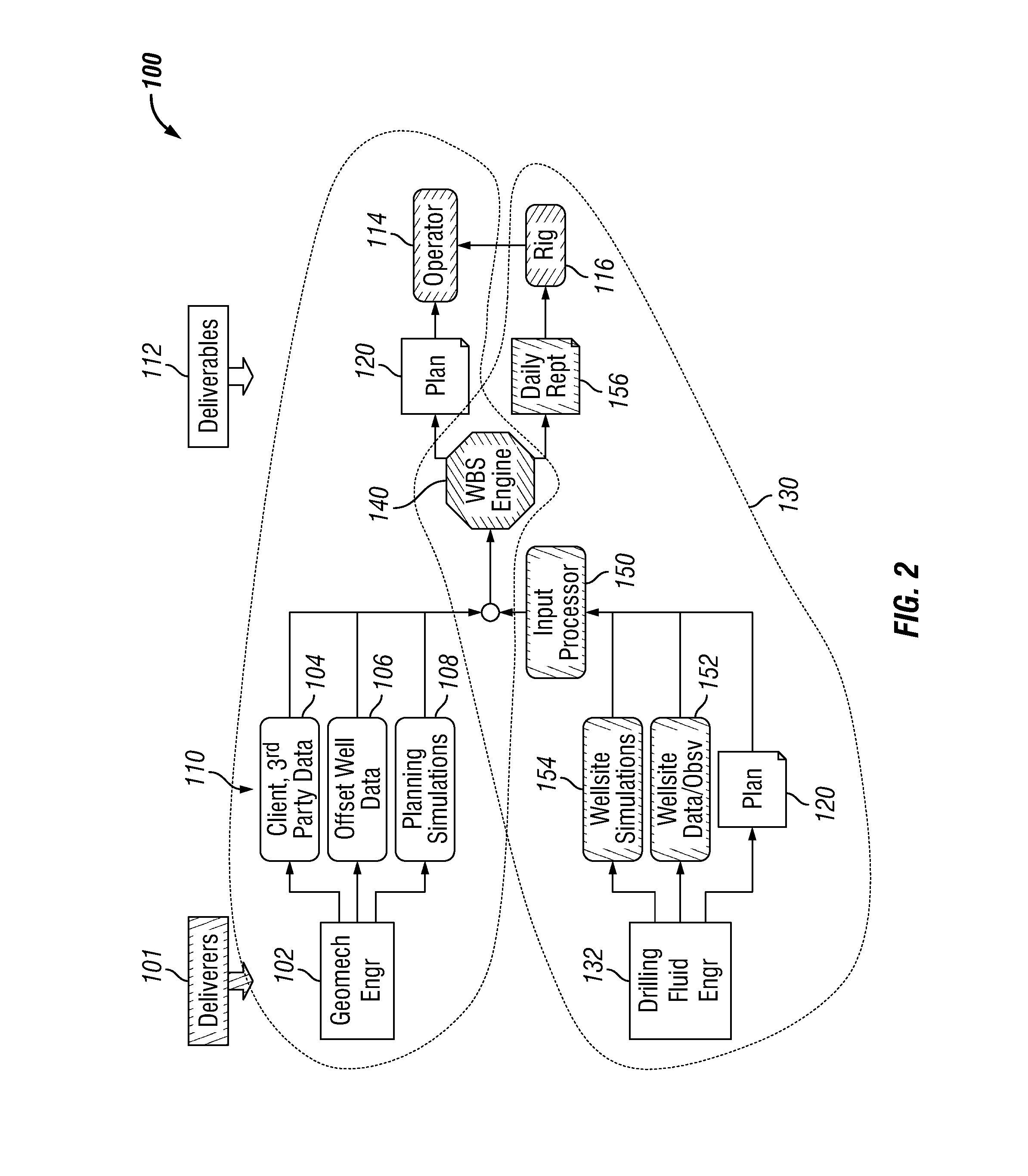
This patent is about a method and system for reducing wellbore instability during drilling. The method involves using pre-drilling assessment information, a well plan, and data measured at the wellsite to integrate these factors and adjust drilling fluid parameters in real-time. This system of combining geomechanics and drilling fluids engineering can improve wellbore stability, reduce wellbore instability and improve the overall quality of drilling.

Problems solved by technology

However, their efforts are often out of sync with regard to time frame, data resources, uncertainties, responsibilities, and sense of urgency.
Attempts to resolve these issues in the past have encountered mixed results, primarily because the two groups utilize different technology and communicate differently.
However, drilling fluid engineers charged with recommending and maintaining proper mud weights rarely have access, training, or time to execute geomechanical software as part of their duties.
Likewise, geomechanical engineers rarely get continual updates (unless problems are encountered) and their software usually is not designed to handle certain types of data, including fuzzy data provided by wellsite drilling personnel.
Wellbore instability is one underlying cause of non-productive time during well construction.
While a diversity of parameters affect the instance and degree of instability, factors including downhole mud density and equivalent circulating density profiles can contribute to wellbore instability when these densities are not appropriate for a particular formation or well profile, especially in highly deviated wells.
This multi-pronged approach, may result in uncertainty, lose effectiveness when information and resources are not readily available or the information is not communicated with everyone involved in making decisions and implementing solutions.

Method used


Image

  • Method Of Minimizing Wellbore Instability
  • Method Of Minimizing Wellbore Instability
  • Method Of Minimizing Wellbore Instability

Examples


Embodiment Construction

[0012]To define more clearly the terms used herein, the following definitions are provided. To the extent that any definition or usage provided by any document incorporated herein by reference conflicts with the definition or usage provided herein, the definition or usage provided herein controls.

[0013]The term “wellbore stability” is used herein to mean

[0014]The term “equivalent circulating density” is used herein to mean the effective density exerted by a circulating fluid against the formation that takes into account the pressure loss in the annulus above the depth being considered.

[0015]The term “equivalent static density” is used herein to mean the effective density a depth of interest of a static column of fluid exposed to downhole temperatures and pressures.

[0016]The term “high temperature / high pressure” is used herein to mean a well having an undisturbed bottomhole temperature of greater than 300° F. [149° C.] and a pore pressure of at least 0.8 psi / ft (˜15.3 lbm / gal).

[0017]...


PUM


Abstract

A process for reducing wellbore instability includes inputting pre-drilling assessment information into an hydraulics analysis and wellbore stability application, inputting a well plan into the hydraulics and wellbore analysis application, inputting a parameter measured at the wellsite into the hydraulics and wellbore stability analysis application, inputting an observation made at the wellsite into the hydraulics and wellbore stability analysis application, integrating the pre-drilling assessment information, the measured parameter, and the observation into the wellbore strengthening analysis application, and adjusting a drilling fluid parameter in response to the integrated pre-drilling assessment information, the measured parameter, and the observation.

Description

BACKGROUND OF INVENTION[0001]Geomechanical and drilling fluid engineers share the common goal of maintaining proper mud weights to minimize wellbore instability during drilling. However, their efforts are often out of sync with regard to time frame, data resources, uncertainties, responsibilities, and sense of urgency. Attempts to resolve these issues in the past have encountered mixed results, primarily because the two groups utilize different technology and communicate differently.[0002]Wellbore stability planning on complex wells is the domain of geomechanical engineers who base their recommendations on offset log analyses, well histories, geomechanical models, and knowledge of the area. Using these recommendations as guidelines, rig personnel respond to changing and unexpected well conditions by continually monitoring and adjusting mud properties and drilling practices. However, drilling fluid engineers charged with recommending and maintaining proper mud weights rarely have acc...

Claims


Application Information

Patent Timeline
Patent Type & Authority Applications(United States)
IPC IPC(8): E21B43/00
CPCE21B43/00E21B44/00
Inventor ZAMORA, MARIOGUO, QUANXINROY, SANJIT
Owner MI
Learn More