
Wireless bearing building method, access point equipment, user equipment and system

a building method and technology for wireless bearings, applied in the direction of wireless commuication services, network traffic/resource management, electrical equipment, etc., can solve the problems of poor experience of subscribers, high implementation complexity, inefficient and costly to bear the large-traffic low-speed ip data packet services, etc., to achieve the effect of reducing the signalling load of the core network and high implementation complexity

Active Publication Date: 2014-01-30
DATANG MOBILE COMM EQUIP CO LTD
View PDF5 Cites 28 Cited by
  • Summary
  • Abstract
  • Description
  • Claims
  • Application Information

AI Technical Summary

Benefits of technology

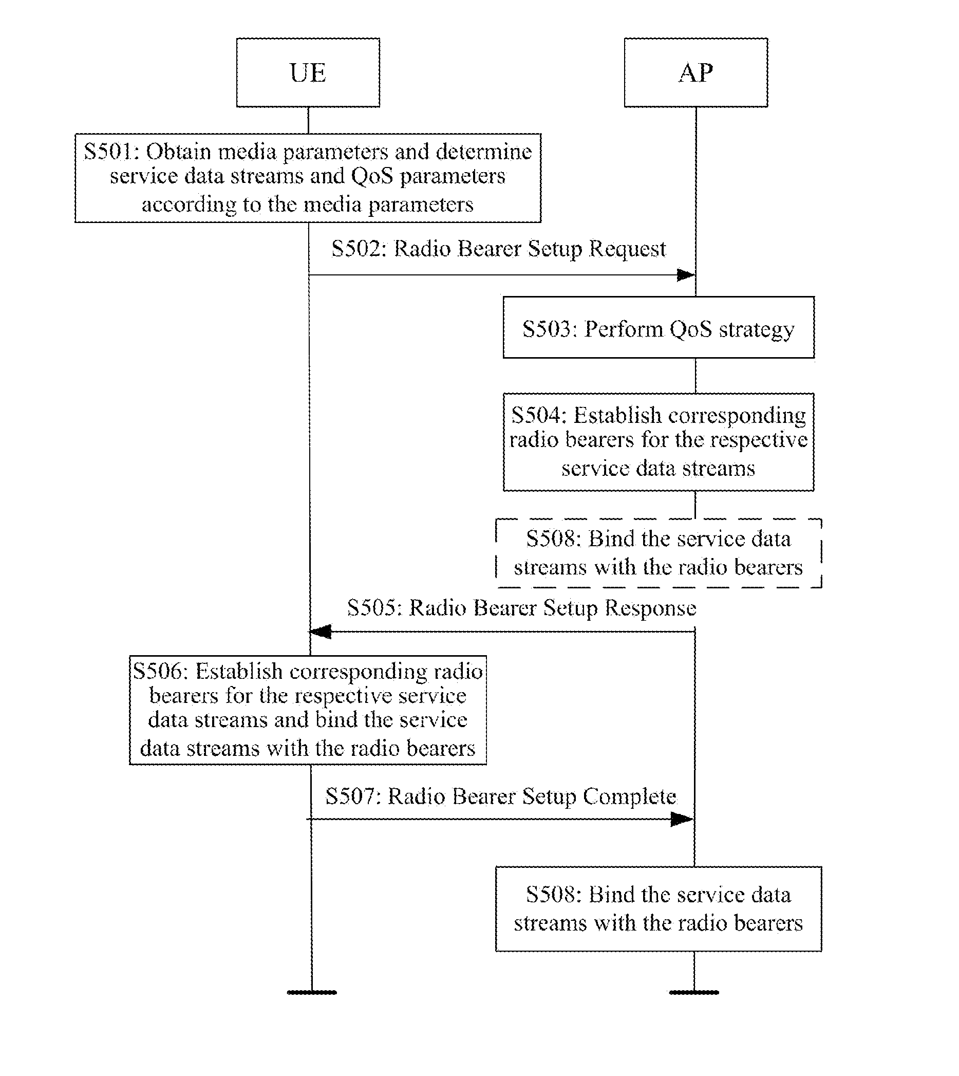
The invention provides a new radio access network and a new method of establishing a radio bearer, a UE and an AP apparatus that are adapted to the new network. The network can provide a telecommunication-level QoS-guaranteed service to the UE without involving the core network and alleviating the problem of failing to provide a QoS-guaranteed service and avoiding the high implementation complexity and heavy signalling load of the core network in existing solutions. The method involves segmenting IP data streams of a service application into multiple service data streams with different QoS parameters, and determining whether these streams can be served based on a local QoS strategy. The network then allocates and binds radio resources and establishes corresponding radio bearers for each service data stream to transmit data by mapping each stream to a corresponding radio bearer for transmission according to its QoS parameters. This ensures a perfect QoS service mechanism in the network.

Problems solved by technology

Since a traditional cellular mobile communication system is generally designed for the high-speed mobile telecommunication-level services with seamless switching, it may be inefficient and costly to bear the large-traffic low-speed IP data packet services.
The use of the foregoing architecture to cover a hotspot area can better offload a data service, but the use of the two different standard frameworks and systems results in a poor experience of subscribers and is limited by the WLAN radio access technology, the network can not provide the subscribers with a QoS guaranteed service; and a link quality is unstable exposed to interference of other systems.
However, a drawback thereof lies in that the home eNB or Femto has not been optimized for the low mobility or nomadic mobility characteristic of the data service indoors, and taking the LTE Femto system as an example, the LTE Femto substantially adopts the entire LTE protocol architecture and interface design with the support of a UE handover and is complex to implement despite reductions in capacity and power of the eNB and consequently still highly expensive.
Moreover, in the home eNB network, the majority of communication process flows of UEs have to be controlled and managed by the 3GPP core network, and data packets of the UEs for an access to the Internet and other external networks have to be forwarded by the 3GPP core network, thus bringing considerable signalling and data loads to the core network.
This architecture also makes the home eNB network fail to be optimized in view of the characteristics of a local access of the subscribers indoors and in a hotspot area to the external networks.
In view of the issues of an access and coverage indoors and in a hotspot area, the architecture of the LTE Femto system is complex and costly, and a communication process of the UEs may bring a considerable load impact on the 3GPP core network, and the WLAN technology fails to provide the UEs with telecommunication-level QoS guaranteed services despite its simple network deployment.

Method used


Image

  • Wireless bearing building method, access point equipment, user equipment and system
  • Wireless bearing building method, access point equipment, user equipment and system
  • Wireless bearing building method, access point equipment, user equipment and system

Examples


Embodiment Construction

[0043]A method of establishing a radio bearer, a user equipment, an access point apparatus and a radio access system according to embodiments of the invention will be described below in details with reference to the drawings.

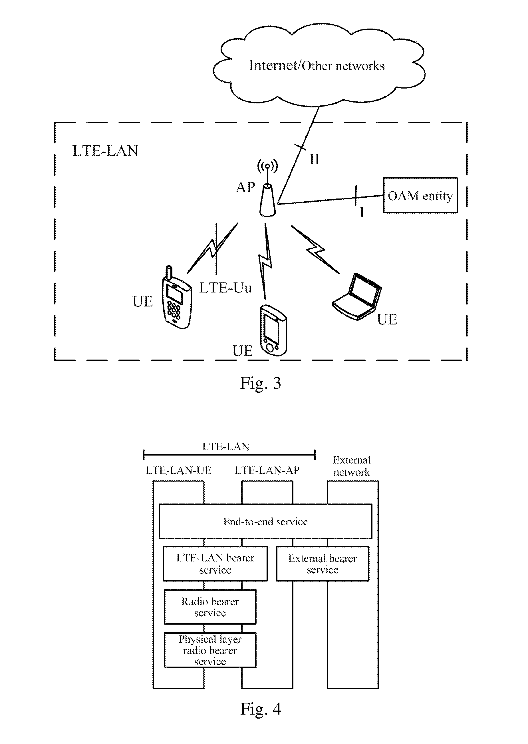
[0044]The method of establishing a radio bearer, the user equipment, the access point apparatus and the radio access system according to embodiments of the invention are based upon the architecture of a Long Term Evolution Local Area Network (LTE-LAN) framework according to an embodiment of the invention, and firstly the architecture of this LTE-LAN framework will be described below briefly.

[0045]In order to enable effective coverage of hotspot areas in home and enterprises environments and to provide means of communication with a large amount of data for user equipments with the characteristic of nomadic mobility, an embodiment of the invention provides an LTE-LAN system architecture implemented with low layer communication technologies of an LTE mobile communi...


PUM


Abstract

Disclosed in the present invention are a wireless bearing building method, an Access Point (AP) equipment, a User Equipment (UE) and a wireless access system, the UE divides the IP date flow of a service into multiple service date flow having different QoS requirements according to media parameter information, determines QoS parameters of each service date flow and sends the information of the service date flow and the corresponding QoS parameters to the AP, the AP allocates wireless resources for each service date flow according to the local QoS strategy, builds the corresponding wireless bearing and binds the service date flow and the wireless bearing; the UE side also builds the corresponding wireless bearing for each service date flow and binds the service date flow and the wireless bearing, during the uplink and downlink date transmission, the AP and UE in the present invention can map each service date flow to the corresponding wireless bearing respectively for transmission according to the QoS requirements of different service date flow, implements perfect service mechanism of the QoS.

Description

[0001]The present application claims priority to Chinese Patent Application No. 201110034298.4, filed with the State Intellectual Property Office of China on Jan. 31, 2011 and entitled “Method of establishing radio bearer, access point apparatus, user equipment and radio access system”, which is hereby incorporated by reference in its entirety.FIELD OF THE INVENTION[0002]In recent years, there is a dramatically increasing demand for mobile data traffic along with the popularization of the Mobile Internet and smart cellular phones, and indoor data services take a significant proportion thereof. Indoor and hotspot data services are characterized by typical immobility or very-low-speed mobility (nomadic mobility) of subscribers with a low mobility requirement; and on the other hand, the data services are generally Internet Protocol (IP) based Internet services with a unified Quality of Service (QoS) requirement far below a QoS requirement of telecommunication-level services. Since a tr...

Claims


Application Information

Patent Timeline
Patent Type & Authority Applications(United States)
IPC IPC(8): H04W72/08H04W72/54
CPCH04W72/087H04W28/24H04W72/543
Inventor TIAN, YEZHAO, JINBOLIU, YANG
Owner DATANG MOBILE COMM EQUIP CO LTD
Learn More