
Apparatus and method for discontinuous reception in multiple component carrier system

a carrier system and antenna technology, applied in the field of wireless communication, can solve the problems of inability to substantially change the frequency bands allocated to the respective link, inability to provide frequency resources, and limitation of fdd scheme efficiency

Inactive Publication Date: 2014-01-30
PANTECH CO LTD
View PDF2 Cites 75 Cited by
  • Summary
  • Abstract
  • Description
  • Claims
  • Application Information

AI Technical Summary

Benefits of technology

The present invention provides an apparatus and method for discontinuous reception on the basis of a half-duplex UE operation in a multiple component carrier system. The invention also provides a reference for counting an active time in a case in which multiple serving cells are configured in a UE. The invention further provides an apparatus and method for performing a discontinuous reception operation on the basis of a concept of a PDCCH subframe defined from a vantage point of multiple serving cells in a half-duplex UE operation. The technical effect of the patent text is to improve the efficiency of data transmission and save power in a multiple component carrier system.

Problems solved by technology

However, frequency bands of respective links configured according to the FDD scheme are required to be spaced apart from each other by a predetermined frequency due to interference is between links, causing some frequency resources to be unavailable.
Also, frequency bands allocated to the respective links cannot be substantially changed.
Thus, in an asymmetric service, such as file transmission or an Internet service, in which an amount of radio resources required for each link may be changed over time, radio resources used in downlink and uplink in a wireless transmission / reception system are determined in advance, so the FDD scheme has limitation in efficiency.
Thus, if time synchronization is not matched for transmission and reception in each device, unintentional interference signals are generated between devices, degrading performance.
The reason is because, a frequency separation between serving cells in a band is close, so if different uplink and downlink configurations are allocated to each serving cell, uplink and downlink operations are performed at the same point in time, causing interference between serving cells.

Method used


Image

  • Apparatus and method for discontinuous reception in multiple component carrier system
  • Apparatus and method for discontinuous reception in multiple component carrier system
  • Apparatus and method for discontinuous reception in multiple component carrier system

Examples


Embodiment Construction

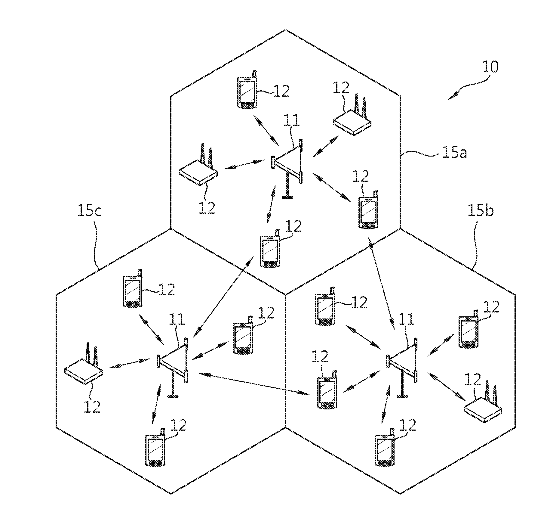
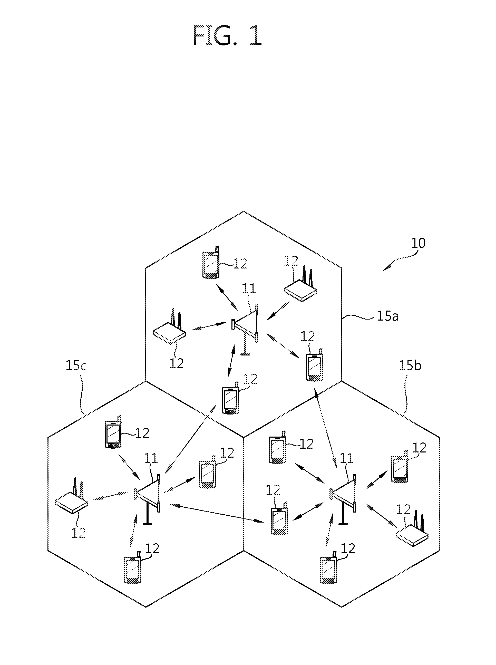
[0039]Hereinafter, in the present disclosure, some embodiments will be described in detail with reference to the accompanying drawings, in which like numbers refer to like elements throughout although they are shown in different drawings. In describing the present invention, if a detailed explanation for a related known function or construction is considered to unnecessarily divert the gist of the present invention, such explanation will be omitted but would be understood by those skilled in the art.

[0040]In the present disclosure, a wireless communication network will be described, and an operation performed in the wireless communication network may be performed in a is process of controlling a network and transmitting data by a system (e.g., a base station (BS)) administering the corresponding wireless communication network or may be performed in a user equipment (UE) connected to the corresponding wireless network.

[0041]According to embodiments of the present invention, meaning o...


PUM


Abstract

An apparatus and method for discontinuous reception in multiple component carrier system are provided. A method for a discontinuous reception (DRX) operation by a half-duplex UE in multiple component carrier system includes identifying whether a current subframe is a physical downlink control channel (PDCCH) subframe; perform PDCCH monitoring on the identified PDCCH subframe during an active time of a DRX cycle; and counting a DRX-related timer included in the active time in the identified PDCCH subframe.

Description

CROSS-REFERENCE TO RELATED APPLICATION[0001]This application claims priority from and the benefit under 35 U.S.C. §119(a) of a Korean Patent Application No. 10-2012-0080779, filed on Jul. 24, 2012, which is incorporated by reference for all purposes as if fully set forth herein.BACKGROUND[0002]1. Field[0003]The present invention relates to wireless communication and, more particularly, to an apparatus and method for discontinuous reception in multiple component carrier system.[0004]2. Discussion of the Background[0005]In general, radio resources used in wireless communication are defined in a is frequency domain, a time domain, and a code domain. In wireless communication, a user equipment (UE) and a base station (BS) are supposed to use given radio resource, respectively. A wireless path for a UE to transmit a signal to a BS is known as uplink and a wireless path for a BS to transmit a signal to a UE is known as downlink. Meanwhile, a scheme for discriminating between radio resourc...

Claims


Application Information

Patent Timeline
IPC IPC(8): H04W76/04
CPCH04W76/048H04W76/28H04L5/001H04L5/16H04W76/20
Inventor KWON, KI BUMAHN, JAE HYUNHUH, KANG SUK
Owner PANTECH CO LTD
Learn More