
Hybrid welding system and method of welding

Inactive Publication Date: 2014-01-30
GENERAL ELECTRIC CO
View PDF1 Cites 29 Cited by
  • Summary
  • Abstract
  • Description
  • Claims
  • Application Information

AI Technical Summary

Benefits of technology

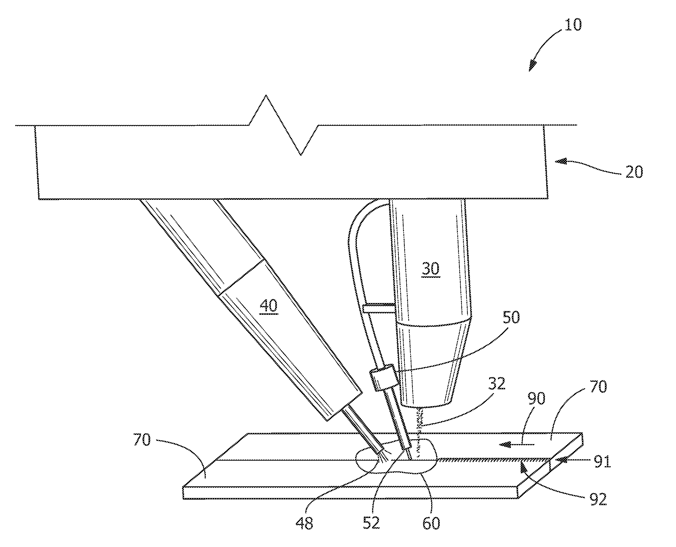
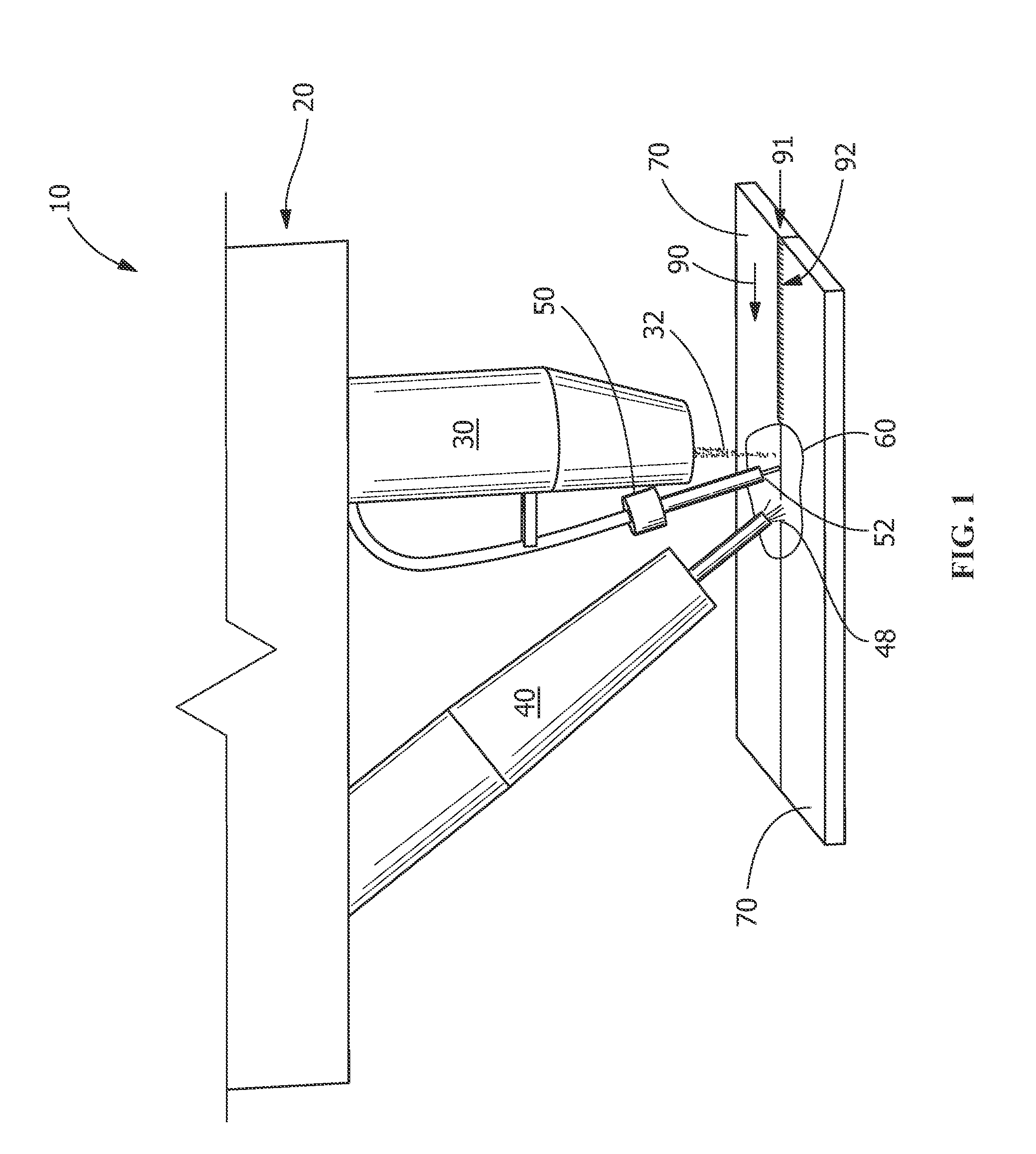
The present patent is about a hybrid welding system that combines a laser and an electric arc welder. The laser and electric arc welder are positioned to direct energy towards adjacent components to form a shared molten pool. A wire feeding device is located between the laser and electric arc welder and is designed to feed a wire into the shared molten pool to join the components without splattering and at a high constant weld speed. The technical effect of this hybrid system is to allow for efficient and precise welding with reduced costs and improved quality.

Problems solved by technology

Although a hybrid laser arc welder with a consumable electrode arc welder, a GMAW, for example, may allow for a high welding deposition rate and welding speed up to 120 inches per minute in mild-steel, low alloy steel, structural steel, and stainless steel, splattering is an unwanted side effect.
The cleaning step is an additional processing step that requires additional time and labor.
In addition, if the wire is delivered to the front of the electric arc welder in the arc leading case, the arc from the GTAW or PAW will have to melt the delivering wires, which also limits the welding speed.

Method used


Image

  • Hybrid welding system and method of welding
  • Hybrid welding system and method of welding
  • Hybrid welding system and method of welding

Examples


reference example 1

[0032]As shown in FIGS. 4 and 5, the first reference example includes joining two adjacent components 70 using a welding device. Welding device includes laser 30 having beam 32 and a consumable electrode electric arc welder 43. In this reference example, the consumable electric arc welder 43 is a GMAW torch with a consumable electrode 45 and a consumable electrode feeding device 47 for feeding consumable electrode 45. The welded components 70 were ⅛″ thick stainless steel (SS304, with a chemical composition of about 8-11% Ni, about 17.5-20% Cr, about 2% Mn, with balance Fe, available from Grainger Industrial Supply, Greer, S.C.) with a shear edge. The welding speed was 80 set to inches per minute (ipm). Laser 30 power was set at 4.0 kW and GMAW torch 43 setting was 230 ipm with a filler metal stainless steel (55308L, with a chemical composition of about 9-11% Ni, about 19.5-22% Cr, about 1.0-2.5% Mn with balance FE) and wire having a 0.889 millimeter (0.035 inch) diameter. As shown ...

reference example 2

[0033]As shown in FIGS. 7 and 8, second reference example includes joining two adjacent components 70 using a welding device. Welding device includes laser 30 having beam 32, non-consumable electrode electric arc welder 40, and wire feeding device 50. Wire feeding device 50 is in front of laser 30. Non-consumable electrode electric arc welder 40 is a GTAW torch 41. Wire feeding device 50 feeds wire 52 in front of laser 30 and GTAW torch 41. As shown in FIG. 7, wire feeding device 50 leads laser 30 in weld direction 90. In this reference example, welded components 70 were ⅛″ thick stainless steel (SS304) with a shear edge. The welding speed was set to 80 ipm. Laser 30 power was set at 4 kW (maximum setting) and the GTAW torch 41 setting was 218 A / 18V (maximum setting). The wire feeding speed of wire feeding device 50 was 230 ipm with a filler metal 308L wire 50 having diameter of about 0.889 millimeters (0.035 inches). The incomplete weld obtained from this example is shown in FIG. 8...

example 3

Present Disclosure

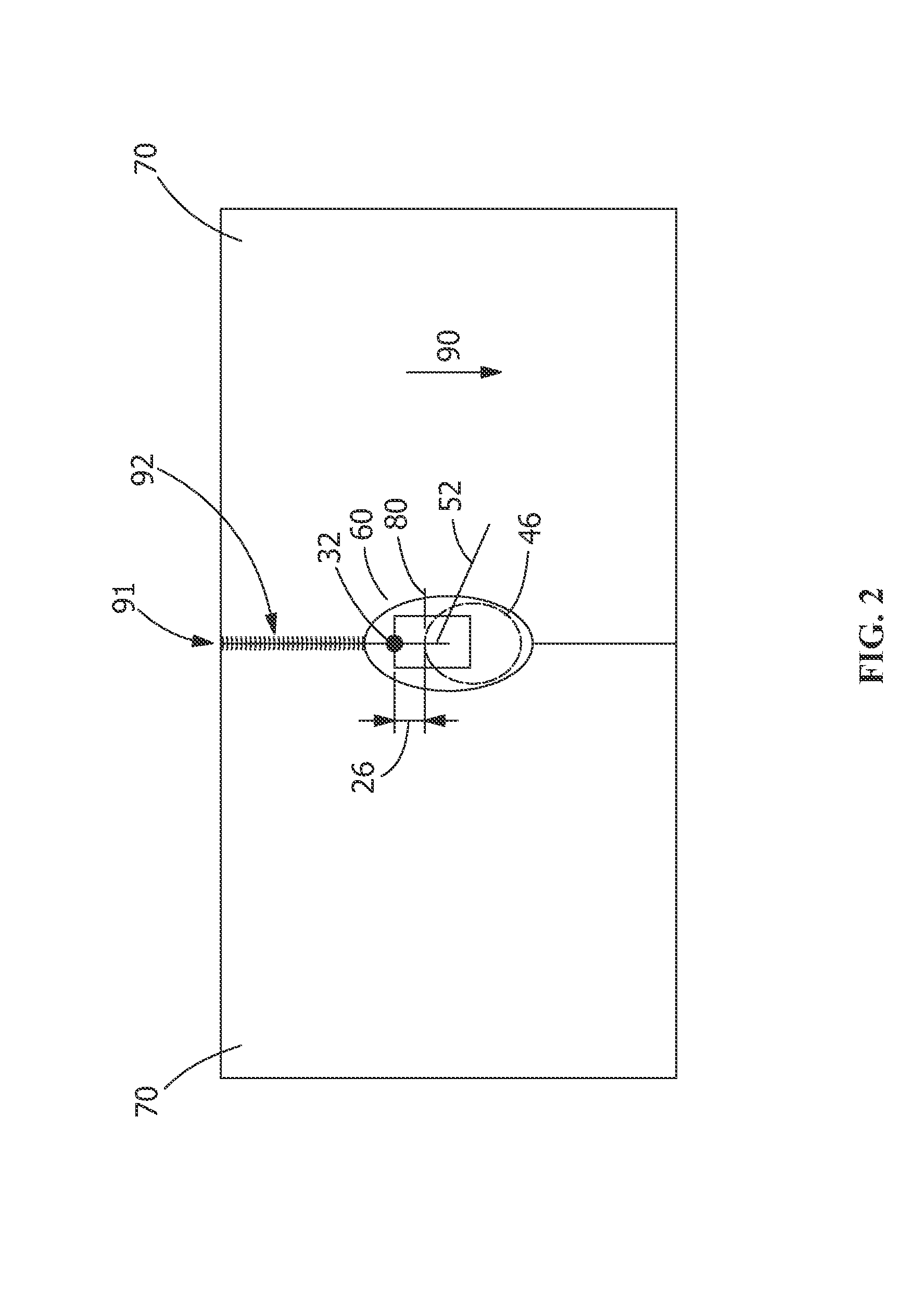
[0034]As shown in FIGS. 9 and 10, an example of the present disclosure is provided. The present disclosure joins two adjacent components 70 using hybrid welding apparatus 20. In the present disclosure, the welded components 70 were ⅛″ thick stainless steel (SS304) with a shear edge. Hybrid welding apparatus 20 includes laser 30 and non-consumable electrode electric arc welder 40, and wire feeding device 50 between laser 30 and electric arc welder with non-consumable electrode 40. In this embodiment, non-consumable electric arc welder 40 is a GTAW torch 41. Laser 30 power was set to 3.6 kW and GTAW torch, is set at 200 A / 18V. As shown in FIG. 9, laser 30 leads in welding direction 90. The welding speed was 80 ipm. Wire 50 feeding speed was 230 ipm with a filler metal 55308L having a 0.889 millimeter (0.035 inch) diameter and directed to shared molten pool 80 forming common molten pool 60 (see FIG. 2). As shown in FIG. 10, full penetration weld 92 including top weld ...


PUM

PropertyMeasurementUnit
Diameteraaaaaaaaaa
Diameteraaaaaaaaaa
Speedaaaaaaaaaa

Abstract

A hybrid welding system including a hybrid welding apparatus and method of welding are provided. The hybrid welding apparatus includes a laser, an electric arc welder with a non-consumable electrode and a wire feeding device. The electric arc welder provides an electric arc without feeding a welding wire. The wire feeding device is arranged and disposed to feed a wire to a treatment area, which is located between the projections of laser beam and the electric arc. The laser and the electric arc welder are arranged and disposed to direct energy toward at least two adjacent components to form a common molten pool. The wire is fed by the wire feeding device into the common molten pool created by the laser and the electric arc.

Description

FIELD OF THE INVENTION[0001]This invention relates to joining technology generally, and specifically, to a hybrid welding system and apparatus and a method for joining components using hybrid welding technology.BACKGROUND OF THE INVENTION[0002]Hybrid laser arc welding is a method of welding two pieces of metal together which typically combines laser beam welding with electric arc welding, for example, on the same side of a joint between the pieces of metal to simultaneously direct both a laser beam and an electric arc at one welding zone to produce a common molten metal pool which solidifies to form a weld.[0003]Electric arc welders of the hybrid laser arc welder include welders having consumable electrodes, such as, but not limited to, a gas metal arc welder (GMAW), a flux cored arc welder (FCAW) and welders having non-consumable electrodes with wire feeding, such as, but not limited to, a gas tungsten arc welder (GTAW) with wire feeding and a plasma arc welder (PAW) with wire feed...

Claims


Application Information

Patent Timeline
IPC IPC(8): B23K26/20
CPCB23K9/167B23K28/02B23K26/348
Inventor LIN, DECHAOTOLLISON, BRIAN L.KOTTILINGAM, SRIKANTH CHANDRUDUSCHICK, DAVIDCUI, YAN
Owner GENERAL ELECTRIC CO
Learn More