
Collision detection system, collision detection data generator, and robot

a collision detection and data generator technology, applied in the field of collision detection systems, can solve problems such as difficult to apply techniques to objects, and the occurrence of collisions is an enormous problem

Inactive Publication Date: 2014-01-23
SEIKO EPSON CORP
View PDF32 Cites 44 Cited by
  • Summary
  • Abstract
  • Description
  • Claims
  • Application Information

AI Technical Summary

Benefits of technology

The invention provides a system that can detect collisions even when there is no available data for the objects being analyzed. This system uses a tree structure to perform collision detection processing by analyzing each layer of data sequentially, and can definitively determine if there is a non-collision between two objects based on a layer-by-layer analysis. This simplifies the determination of non-collisions and reduces the complexity of the processing.

Problems solved by technology

For example, in a field of robots or the like, occurrence of collisions is an enormous problem.
However, in practice, a lot of objects without CAD data and objects without available CAD data exist, and there is a problem that it is difficult to apply the technique to the objects.

Method used


Image

  • Collision detection system, collision detection data generator, and robot
  • Collision detection system, collision detection data generator, and robot
  • Collision detection system, collision detection data generator, and robot

Examples


Embodiment Construction

[0058]As below, embodiments of the invention will be explained. Note that the embodiments to be explained do not unduly limit the invention described in the appended claims, and all of the configurations to be explained in the embodiments are not necessarily essential as solving means of the invention.

1. Configuration

[0059]In movements of a robot (manipulator), collisions with peripheral structures and peripheral devices, self-collisions, and collisions with other robots are enormously problematic. In a collision detection technique of the embodiment, the collisions are detected in advance by simulations.

[0060]As modes in which the collision detection technique of the embodiment is used, roughly, off-line use (prior confirmation) and run-time use (prediction, anticipation) are considered. In the off-line use, if the surrounding environment or the like is known and statistic and the movement of the robot is known, the collision is verified at creation of a system. On the other hand, ...


PUM


Abstract

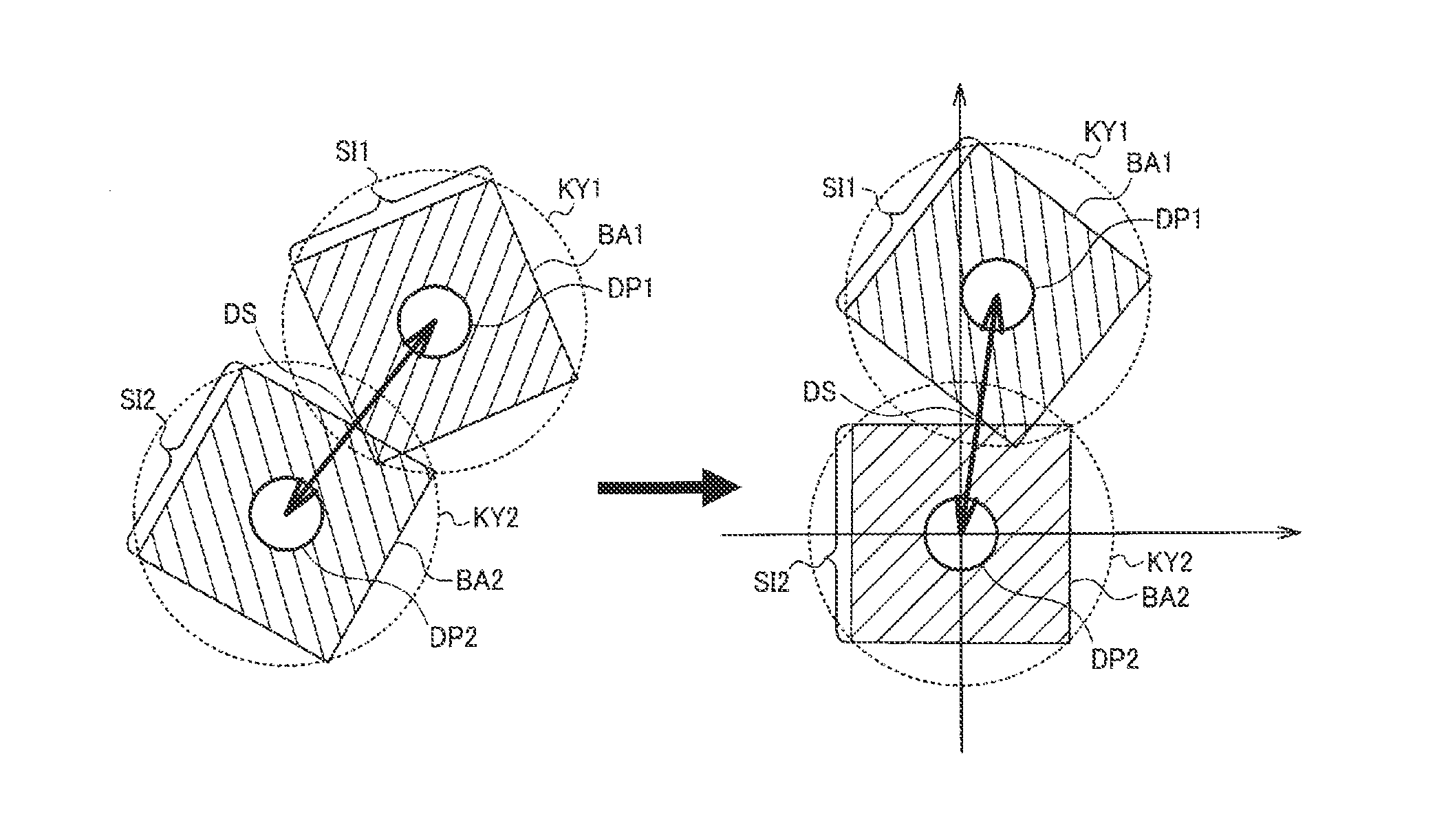
A collision detection system includes a memory unit that stores first collision detection data corresponding to a first object and second collision detection data corresponding to a second object as collision detection data of objects, and a processing unit that performs a collision determination between the first object and the second object in the world coordinate system based on the first collision detection data and the second collision detection data. The memory unit stores representative point data obtained by discretization of depth map data of the objects as seen from a predetermined viewpoint in model coordinate systems of the objects using cubic areas set in the model coordinate systems as the collision detection data.

Description

BACKGROUND[0001]1. Technical Field[0002]The present invention relates to a collision detection system, a collision detection data generator, a robot, or the like.[0003]2. Related Art[0004]Determinations as to whether or not there is a collision between objects or proximity to each other are required in many fields. For example, in a field of robots or the like, occurrence of collisions is an enormous problem. Accordingly, in related art, techniques of determining whether or not a collision or proximity beyond an acceptable level is to occur by calculation using a computer before the collision actually occurs have been studied and developed. As a related art of the collision determination technique, for example, a technology disclosed in Patent Document 1 (JP-A-11-250122) or the like has been known.[0005]In the technique of Patent Document 1, an object is represented by polygon data, the respective polygons of the polygon data are covered by spheres having predetermined radii, those ...

Claims


Application Information

Patent Timeline
Patent Type & Authority Applications(United States)
IPC IPC(8): B25J9/16
CPCB25J9/1666G05B2219/39085G05B2219/39095
Inventor INAZUMI, MITSUHIRO
Owner SEIKO EPSON CORP
Learn More