
Dual-structured electric drive and power system for hybrid vehicles

a hybrid vehicle and electric drive technology, applied in the direction of electric devices, battery/fuel cell control arrangement, electric devices, etc., can solve the problems of reducing powertrain performance and fuel efficiency, small improvement in fuel efficiency, and the least expensive and affordable hybrid technology, so as to reduce the overall weight and size of the apparatus, increase the rotational speed, and reduce the physical size and weight.

Active Publication Date: 2014-01-23
ALTIGREEN PROPULSION LABS
View PDF10 Cites 53 Cited by
  • Summary
  • Abstract
  • Description
  • Claims
  • Application Information

AI Technical Summary

Benefits of technology

The present invention relates to a dual-structured power output apparatus that includes a planetary gear train mechanism and a pulley / timing belt mechanism or an electromechanical control mechanism to increase the rotational speed of one of the electric motors / generators to reduce its size and weight, and improve power density and capability. This apparatus is coupled to a hybrid vehicle powertrain via a serpentine belt, a drive pulley, and a crankshaft pulley to optimize fuel economy. The motor / generators function in both motoring and generating modes and are controlled based on the allocation of electrical power to charge onboard electric energy storage devices and mechanical torque and power to assist the engine. The apparatus includes a planetary gear train mechanism disposed adjacent to the motor / generators for improved power density and capability. The dual-structured power output apparatus and the hybrid vehicle powertrain with the apparatus mounted thereon achieve improvement in fuel efficiency.

Problems solved by technology

Among the roughly four main categories: series, parallel, series-parallel and mild hybrid vehicle technologies on the market today, the mild hybrid technology is the least expensive and affordable.
One functional drawback is that using a single electric motor makes it necessary for frequent mode reversals because it can operate only in one mode (motoring or generating) at a time, and this results in reduced powertrain performance and fuel efficiency.
This operating limitation results in smaller improvement in fuel efficiency.
Another functional drawback of the current state-of-the-art in belt-driven electric motors as utilized in mild hybrid vehicle powertrain technology is that they are typically optimized for one of the operating modes than the other.
Therefore, in a hybrid powertrain that has such an electric motor mounted thereon, in a time period when the power demand requires the electric motor to operate in its less optimized mode, a reduced powertrain performance and fuel efficiency are achieved.
Yet another functional drawback of the current state-of-the-art in belt-driven electric motors as utilized in mild hybrid vehicle powertrain technology is that the electric motors are typically sized based on the peak power.
As a result, they are relatively over-sized, heavier and less efficient in the power range corresponding to the average power demand of the drive cycle.
Therefore, in a vehicle that has such an electric motor mounted thereon, in a time period when the vehicle power demand in accordance with the driving conditions requires the electric motor to operate close to the average power demand, a reduced electric motor performance and fuel efficiency are achieved.
However, all of these prior art patents do not address any of the drawbacks discussed above in order to improve fuel efficiency of a belt-driven parallel hybrid vehicle.
Furthermore, no prior art in hybrid vehicle powertrain technologies and conversion of conventional vehicle into hybrid that use belt-driven electric motors coupled to the engine crankshaft via a special belt has provided solutions that address the functional drawbacks discussed above in order to achieve improvement in fuel efficiency.

Method used


Image

  • Dual-structured electric drive and power system for hybrid vehicles
  • Dual-structured electric drive and power system for hybrid vehicles
  • Dual-structured electric drive and power system for hybrid vehicles

Examples


first embodiment

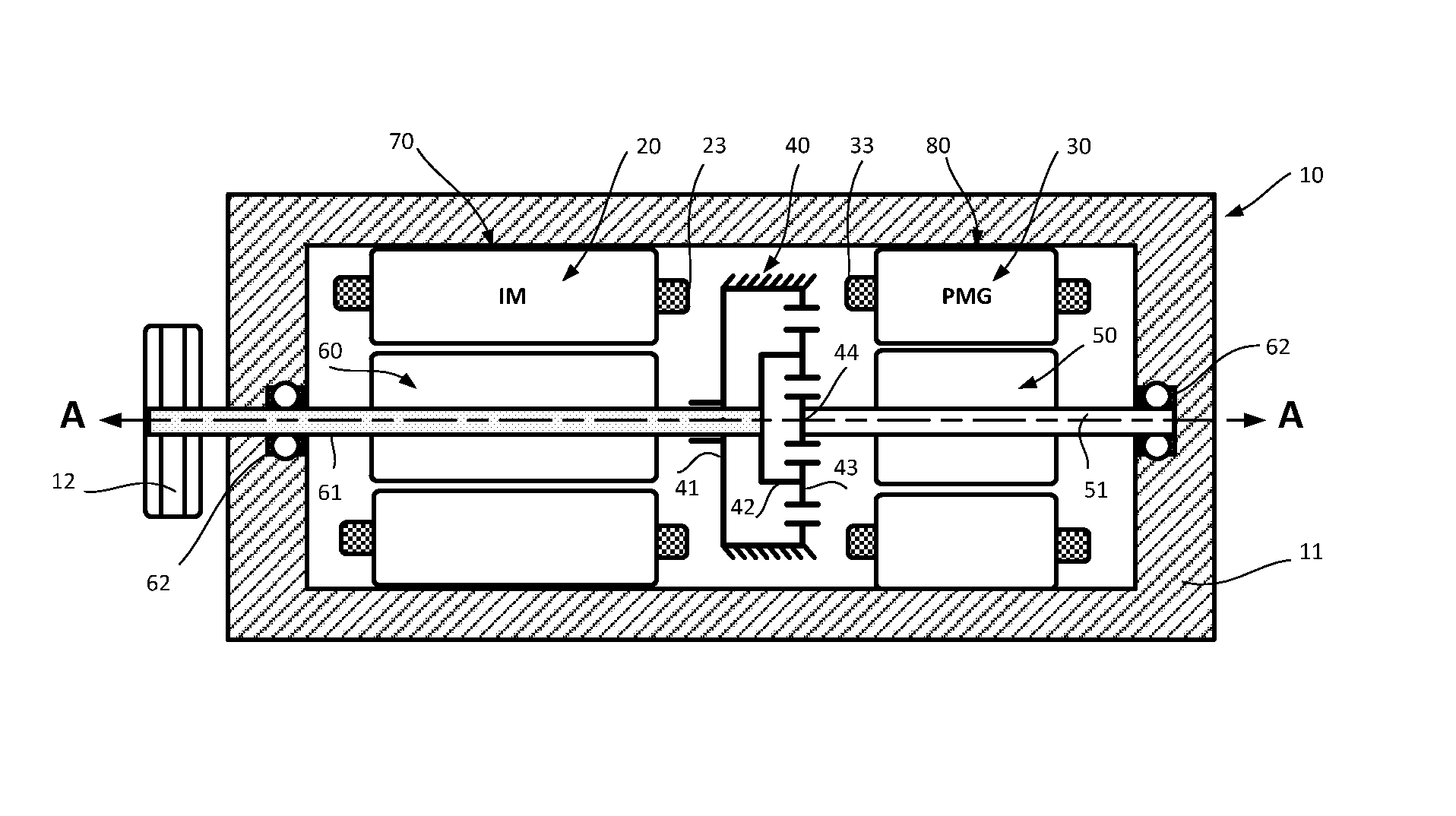
[0032]FIG. 1 illustrates a cross section of a dual-structured power output apparatus assembly 10 (also referred to as “assembly 10”) according to the first embodiment of the present invention. The assembly 10 comprises a first motor / generator M / G1 assembly 70 that includes a stator assembly 20 surrounding a first rotor 60 attached to a first shaft 61; a second motor / generator M / G2 assembly 80 that includes a second stator assembly 30 surrounding a second rotor 50 attached to a second shaft 51; a planetary gear train mechanism 40 axially disposed between the first motor / generator M / G1 assembly 70 and second motor / generator M / G2 assembly 80 that includes a ring gear member 41, a planet carrier member 42 having a plurality of planets 43 mounted thereon and a sun gear member 44; and drive pulley 12 having a plurality of grooves, or sprocket having a plurality of teeth (not shown), that provides a means for coupling and torque transfer to and from crankshaft pulley 19 of a hybrid vehicle...

second embodiment

[0043]A dual-structured power output apparatus in a second embodiment of the present invention is discussed below. FIG. 2 illustrates a cross section of a dual-structured power output apparatus assembly 10 in the second embodiment of the present invention. In this embodiment, the assembly 10 comprises a first motor / generator M / G1 assembly 70, a second motor / generator M / G2 assembly 80 and a planetary gear train mechanism 40. The difference from the first embodiment is that in the second embodiment the ring gear member 41 of the planetary gear train mechanism 40 is not held stationary and rotatable with respect to the main housing. The planetary gear train mechanism 40 includes a ring gear member 41 that is rotatable, a planet carrier member 42 that is freely rotatable and a sun gear member 44 that is rotatable. Hollow shafts having internal splines are formed integrally with the ring gear 41 and sun gear 41 for mechanical coupling with external splines integrally formed on the rotor ...

third embodiment

[0050]A dual-structured power output apparatus in a third embodiment of the present invention is discussed below. FIG. 3 illustrates a cross section of the third embodiment of a dual-structured power output apparatus assembly 10 of the present invention. In this embodiment, the assembly 10 comprises a first motor / generator M / G1 assembly 70, a second motor / generator M / G2 80 and a planetary gear train 40. The first planetary gear train 40 member is a ring gear member 41 that is freely rotatable, the second is a planet carrier member 42 that is rotatable, and the third is a sun gear member 44 that is also rotatable. Hollow shafts having internal splines are formed integrally with the planet carrier 42 and sun gear 41 for mechanical coupling with external splines integrally formed on the rotor shaft 61 and shaft 51 of the first motor / generator M / G1 assembly 70 and second motor / generator M / G2 assembly 80. The planetary gear train mechanism 40 is disposed to effectively utilize the radial...


PUM


Abstract

Disclosed in the present invention is a dual-structured power output apparatus of an electric drive and power system that provides a means for outputting both mechanical power and electrical power. It comprises dual motor / generators having two stator assemblies, two rotor assemblies and a power transmission unit all integrated into a single housing for easy mounting. The power transmission unit is disposed adjacent to the two motor / generators and coupled on both ends to rotating shafts mechanically linked to the rotor assemblies such that they are rotatable relative to each other. It function is to change the rotational speed and torque of at least one of the rotors in order to reduce weight and physical size of the apparatus, and thus significantly improving the power density and capability. The structure of the apparatus is well-suited to improve the performance and fuel efficiency of the prior art hybrid powertrain.

Description

CROSS-REFERENCE TO RELATED APPLICATIONS[0001]This application claims the benefits of the U.S. Provisional Application No. 61 / 741,763, filed on Jul. 17, 2012. The disclosure of the Provisional Application is incorporated herein by reference in its entirety for any and all purposes.BACKGROUND OF THE INVENTION[0002]The present invention pertains to power-assist parallel hybrid vehicles. More specifically, the present invention pertains to a dual-structured power output apparatus that provides a means for outputting both mechanical power and electrical power with high efficiency and is capable of improving fuel efficiency of the prior art hybrid vehicle, as well as to an electric drive and power system and a method of controlling the power output apparatus.[0003]In recent years, the trend in the development of fuel-efficient and low emission hybrid vehicle powertrain technologies that combine a conventional combustion engine (ICE) with an electric propulsion system has increased signifi...

Claims


Application Information

Patent Timeline
IPC IPC(8): B60W20/00F16H37/06B60L50/15B60L50/16
CPCB60W20/106F16H37/065Y10S903/944F16H37/0826H02K7/116H02K16/00B60L15/2054B60L2210/40B60L2240/12B60L2240/421B60L2240/423B60L2240/425B60L2240/427B60L2240/429B60L2240/441B60L2240/443B60L2250/26B60L7/14B60L15/2009B60L2240/486B60L2220/50B60K1/02B60K6/405B60K6/48B60K6/485B60K2006/266B60K2006/268B60K2006/4833B60L50/61B60L50/16B60L58/12B60K6/26B60K6/365Y10S903/906Y02T10/62Y02T10/64Y02T10/70Y02T10/72Y02T10/7072B60W20/40B60K6/445B60W20/13B60K6/44B60W10/08B60W10/115B60Y2300/66
Inventor BANGURA, JOHN F.MOKLEGAARD, LASSESARAN, AMITABH
Owner ALTIGREEN PROPULSION LABS
Learn More