
Charging a Sacrificial Anode with Ions of the Sacrificial Material

a technology of sacrificial material and anode, which is applied in the direction of building components, building reinforcements, constructions, etc., can solve the problems of unexpected and unacceptable corrosion of steel within the structure, two primary limitations of ordinary galvanic anodes used in steel reinforced concrete, and achieve long-term protection

Active Publication Date: 2014-01-23
VECTOR CORROSION TECH
View PDF9 Cites 10 Cited by
  • Summary
  • Abstract
  • Description
  • Claims
  • Application Information

AI Technical Summary

Benefits of technology

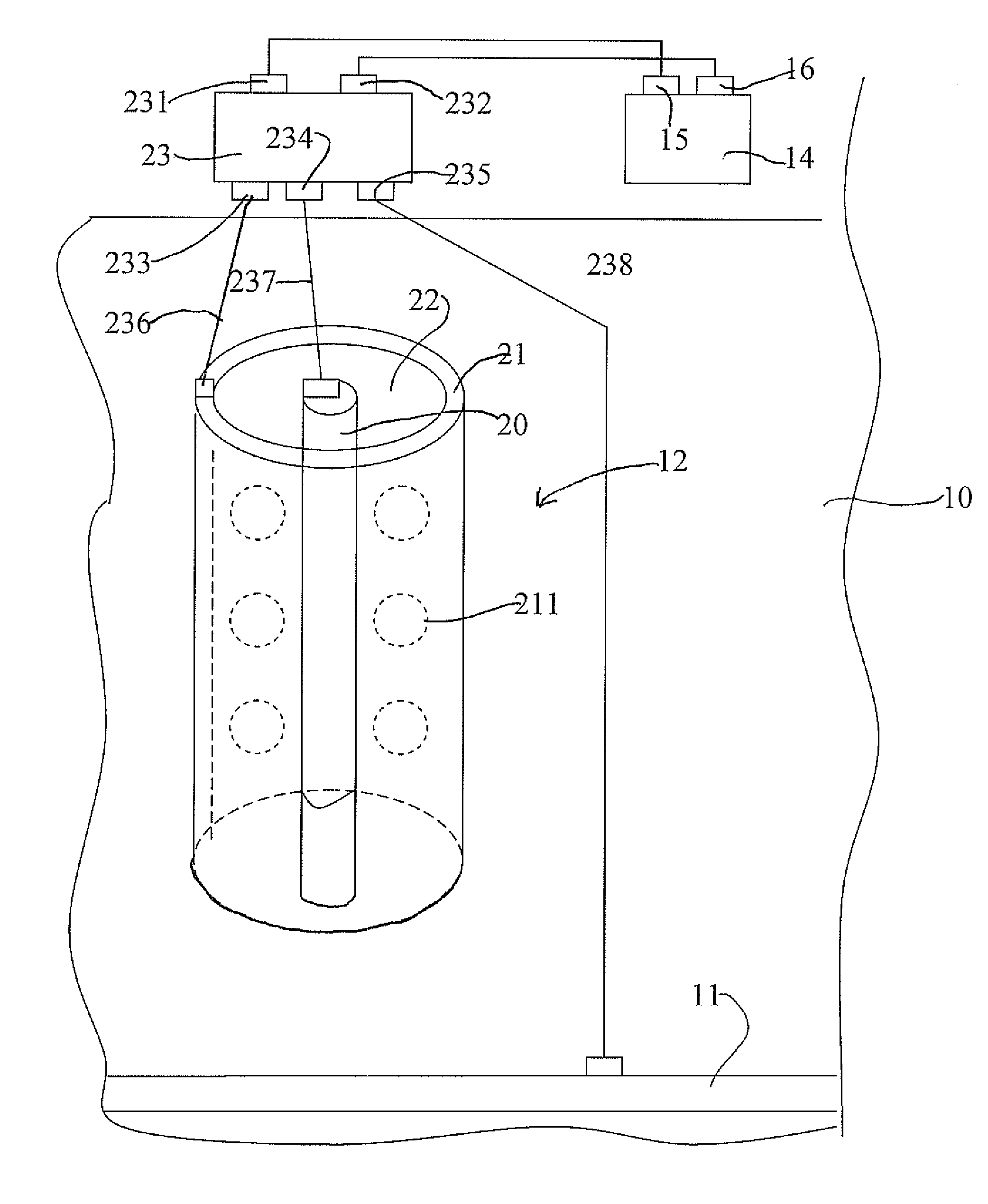
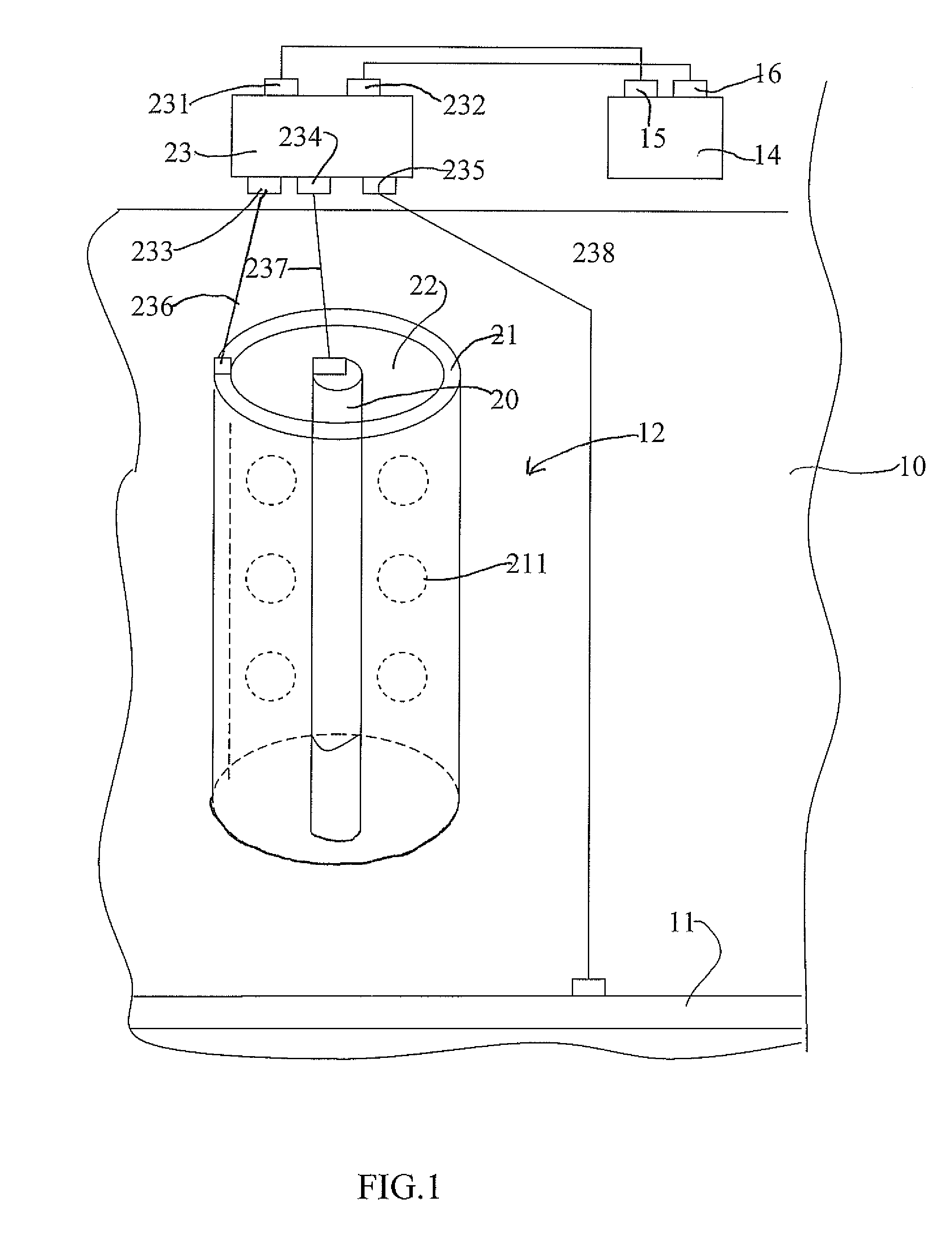
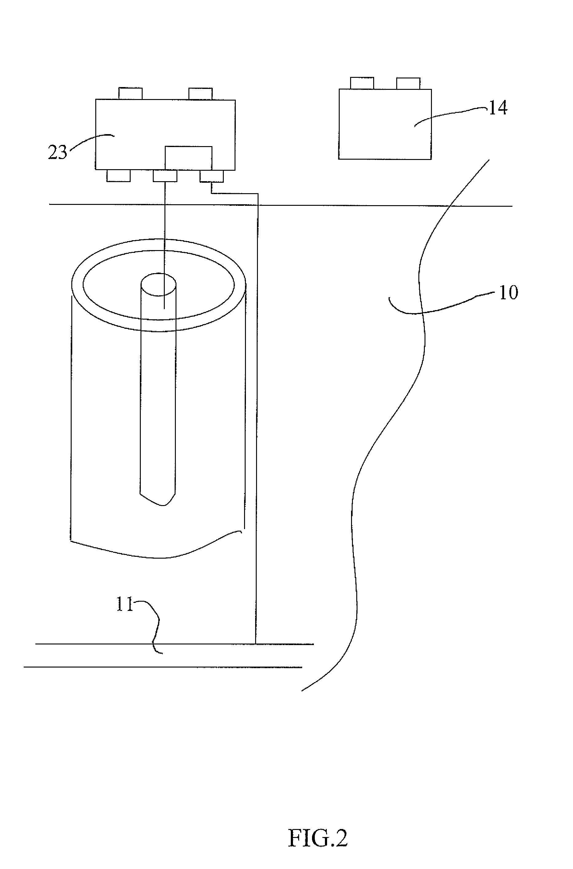
The patent describes a system that uses a sacrificial anode to protect a metal section from corrosion. The sacrificial anode provides cathodic protection, which means it helps to prevent the metal section from becoming the cathode in a corrosion process. The system also includes a solar panel that can be used to power the system and a rechargeable battery to ensure long-term protection, even when the solar power is on and off.

Problems solved by technology

However the patent mentions that other materials such as zinc can be used but these are disadvantageous since they tend to corrode.
In all cases such impressed current systems require regular maintenance and checking of the status of the power supply to ensure that the power supply does not fail leading to unexpected and unacceptable corrosion of the steel within the structure to be protected.
While such maintenance can be carried out and the power supply thus ensured, this is a relatively expensive process.
There are two primary limitations of ordinary galvanic anodes as used in steel reinforced concrete.
The first relates to the mass of zinc per anode which, depending on the required current output, limits the useful life of the anode.

Method used


Image

  • Charging a Sacrificial Anode with Ions of the Sacrificial Material
  • Charging a Sacrificial Anode with Ions of the Sacrificial Material
  • Charging a Sacrificial Anode with Ions of the Sacrificial Material

Examples


example

[0133]In one example, a cast zinc anode, 8 cm long with a minimum diameter of 0.7 cm, was located in ZnO / thixotropic paste packed inside a conductive ceramic impressed current anode tube. The zinc paste was made from a solution saturated with LiOH with 2M KOH and 20% ZnO along with carboxymethyl cellulose sodium thickening agent. The paste was packed in the space between the zinc anode and the inner side of the 28 mm tube. Testing has shown that ions can pass through the porous tube walls such that the zinc anode can pass current onto the external steel reinforcing bar even though it is located inside the impressed current anode. Subsequently, charging of the zinc can be accomplished by reversing the flow of ions through the impressed current porous tubular anode by applying an external voltage between the impressed current anode and the sacrificial anode. An applied voltage of around 6-8 Volts resulted in a current of up to 1.6 A to be delivered to the inner zinc anode achieving a ...


PUM

PropertyMeasurementUnit
voltageaaaaaaaaaa
voltageaaaaaaaaaa
voltageaaaaaaaaaa

Abstract

Cathodic protection of steel in concrete is provided by locating an anode assembly including both a sacrificial anode and an impressed current anode in contact with the concrete and providing an impressed current from a power supply to the anode. The impressed current anode forms a perforated sleeve surrounding a rod of the sacrificial anode material with an activated ionically-conductive filler material between. The system can be used without the power supply in sacrificial mode or when the power supply is connected, the impressed current anode can be powered to provide an impressed current system and / or to recharge the sacrificial anode from sacrificial anode corrosion products.

Description

[0001]This invention relates primarily to a cathodic protection system where a sacrificial anode is charged or recharged with ions of the sacrificial material.BACKGROUND OF THE INVENTION[0002]U.S. Pat. No. 6,346,188 (Shuster) assigned to ENSER Corporation and issued Feb. 12, 2002 discloses a method for cathodic protection of marine piles in which an anode is located within a jacket surrounding the pile at water level and a battery is mounted on the pile above the water level for providing an impressed current between the anode of the jacket and the steel of the pile. The anode is preferably formed of titanium or other non-corroding materials which are high on the Noble scale. However the patent mentions that other materials such as zinc can be used but these are disadvantageous since they tend to corrode. The intention is that the battery have a long life and be maintained effectively so that the impressed current remains in place during the life of the marine pile bearing in mind t...

Claims


Application Information

Patent Timeline
Patent Type & Authority Applications(United States)
IPC IPC(8): C23F13/14
CPCC23F13/14C23F13/06C23F13/20C04B2111/265C23F2201/02C23F2213/22C23F13/04C23F13/08E04C5/015
Inventor SERGI, GEORGESENEVIRATNE, ATTANAYAKE MUDIYANSELAGE GAMINIWHITMORE, DAVID
Owner VECTOR CORROSION TECH
Learn More