
Work Vehicle Having an Exhaust Treatment Apparatus in an Engine Room

Active Publication Date: 2014-01-23
KUBOTA LTD
View PDF2 Cites 37 Cited by
  • Summary
  • Abstract
  • Description
  • Claims
  • Application Information

AI Technical Summary

Benefits of technology

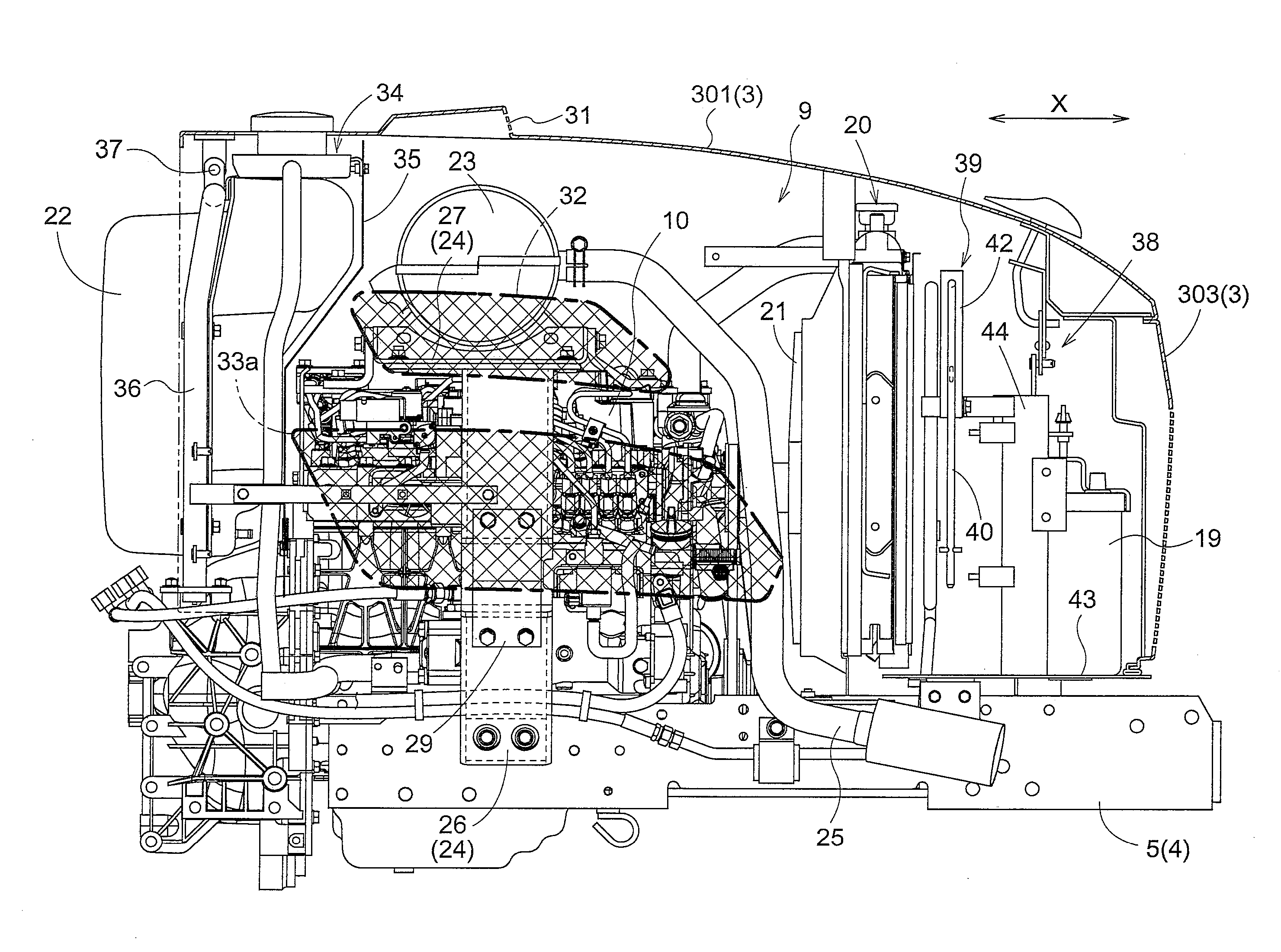
The present invention provides an arrangement for reducing the adverse effects of heated air on components in the lower region of an engine room. This is achieved by using a division member that separates the air into upper and lower portions, guiding the heated air towards the outside of the engine room. The arrangement also includes an exhaust purifying apparatus attached to the division member, which simplifies the overall arrangement and reduces costs. Additionally, the arrangement restricts the air heated by the exhaust purifying apparatus from flowing to the rear side of the engine room and positively guides it towards the opening, thereby appropriately restricting the adverse effect of heat on components in the vicinity of the engine.

Problems solved by technology

Hence, if the air heated by the exhaust purifying apparatus stagnates inside the engine room, this may provide adverse effect by the heat to various components disposed in the vicinity of the engine.
However, with provision of the discharge opening alone, the air in the engine room may not be positively guided to the discharge opening, due e.g. to generation of a turbulent flow inside the engine room, such that the air heated by the exhaust purifying apparatus may not be effectively discharged to the outside.
However, as this partition plate has a special shape, this presents a cost disadvantage.

Method used


Image

  • Work Vehicle Having an Exhaust Treatment Apparatus in an Engine Room
  • Work Vehicle Having an Exhaust Treatment Apparatus in an Engine Room
  • Work Vehicle Having an Exhaust Treatment Apparatus in an Engine Room

Examples


Embodiment Construction

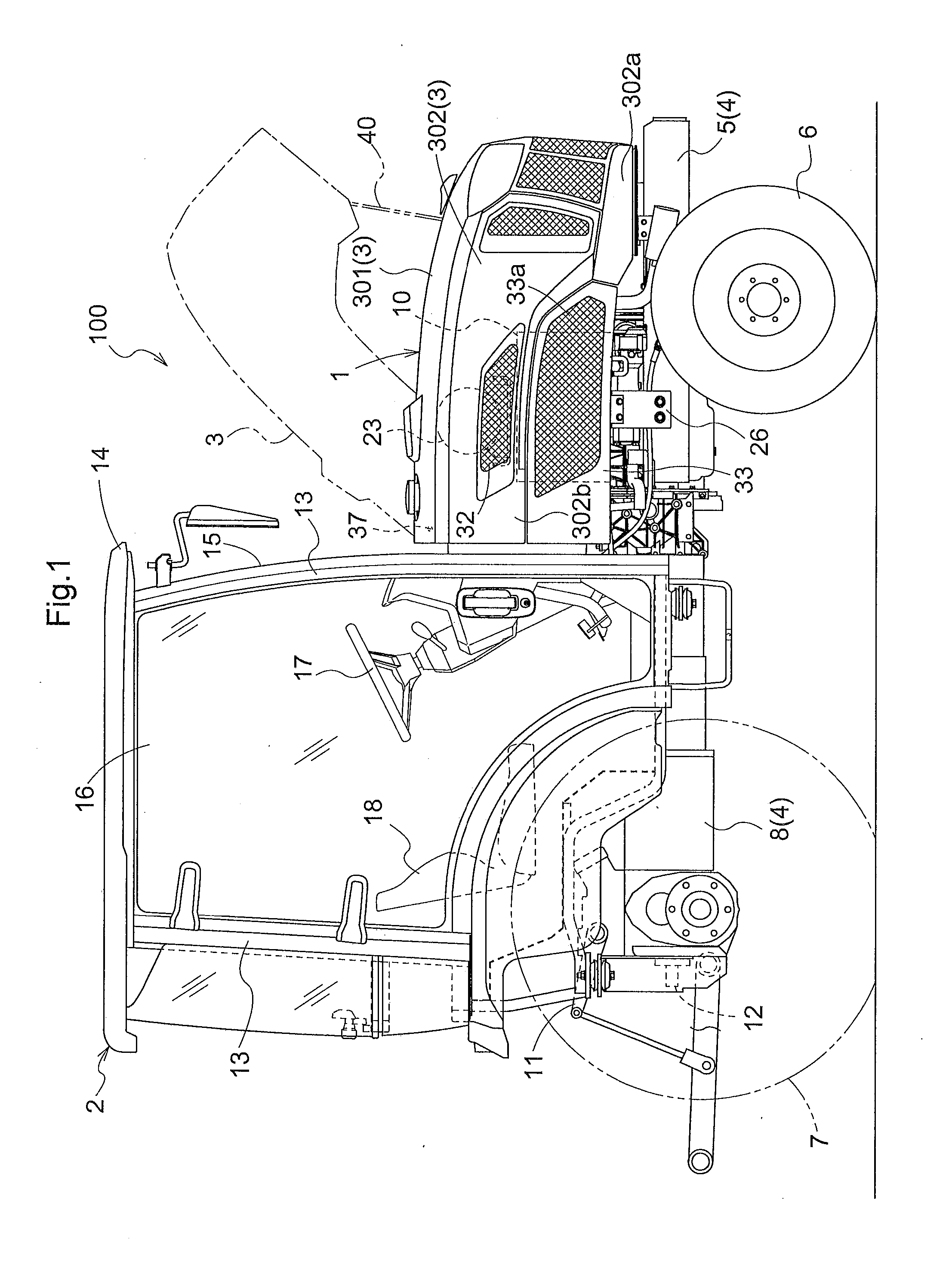
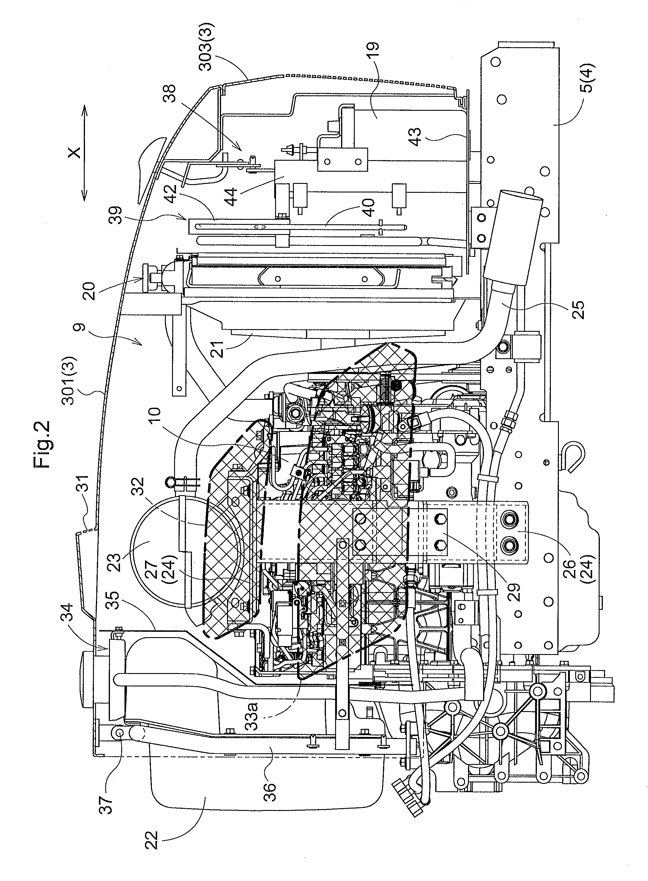
[0034]FIG. 1 shows an overall side view of a tractor with a cabin as an example of a work vehicle relating to the present invention. FIG. 2 is a side view showing the inside of an engine room. FIG. 3 is a plan view showing the inside of the engine room. FIG. 4 is a perspective view showing the inside of the engine room. FIG. 5 is a section view showing the inside of the engine room as seen in a vehicle body fore / aft direction.

[0035]This tractor 100, as shown in FIG. 1, includes an engine section 1 disposed at a front position of the vehicle body and a driver's cabin 2 disposed at a rear position of the vehicle body. The tractor 100 further includes a traveling vehicle body 4 supported by a pair of right and left front wheels 6 and a pair of right and left rear wheels 7. The traveling vehicle body 4 comprises an integrally connected assembly of an engine mount frame 5, a clutch housing (not shown), and a transmission case 8.

[0036]Rearwardly of the transmission case 8, there are provi...


PUM


Abstract

A board-like division member is provided that extends in a vehicle body transverse direction so as to divide a portion of the engine room into an upper region and a lower region along in an engine room height direction. An engine is mounted downwardly of the division member. An exhaust treatment apparatus is mounted upwardly of the division member for treating exhaust gas from the engine. An air discharge portion is formed in a lateral face region of the hood which corresponds to a position of the division member in the engine room height direction. Air present inside the engine room is discharged to the outside through this air discharge portion.

Description

BACKGROUND OF THE INVENTION[0001]1. Field of the Invention[0002]The present invention relates to a work vehicle having, in an engine room, an engine and an exhaust treatment apparatus for treating exhaust gas of the engine.[0003]2. Description of the Related Art[0004]The above-described work vehicle includes an engine hood which can be opened and closed between a closed state for covering the engine from above and an opened state for exposing the upper side of the engine to the outside. Inside the engine room, the engine and the exhaust treatment apparatus are arranged in a predetermined positional relationship relative to each other. For instance, in a work vehicle disclosed in Japanese Unexamined Patent Application Publication No. 2011-126488 (JP 2011-126488 A), an exhaust treatment apparatus is disposed upwardly of the engine. This exhaust treatment apparatus is an exhaust gas purifying apparatus (a DPF: diesel particulate filter) for purifying exhaust gas of the engine.[0005]Suc...

Claims


Application Information

Patent Timeline
IPC IPC(8): B60K11/06B60K13/04B60K5/00
CPCB60K11/06B60K5/00B60K13/04F01N13/1805B60Y2200/221F01N13/1872F01N2260/022
Inventor MASUMOTO, KOJIYANAGIHARA, KATSUMIKUBOTA, MAKOTO
Owner KUBOTA LTD
Learn More