Exhaust gas recirculation apparatus
- Summary
- Abstract
- Description
- Claims
- Application Information
AI Technical Summary
Benefits of technology
Problems solved by technology
Method used
Image

Examples
first embodiment
[0025]A detailed description of a preferred first embodiment of an exhaust gas recirculation apparatus for an engine embodying the present invention will now be given referring to the accompanying drawings.
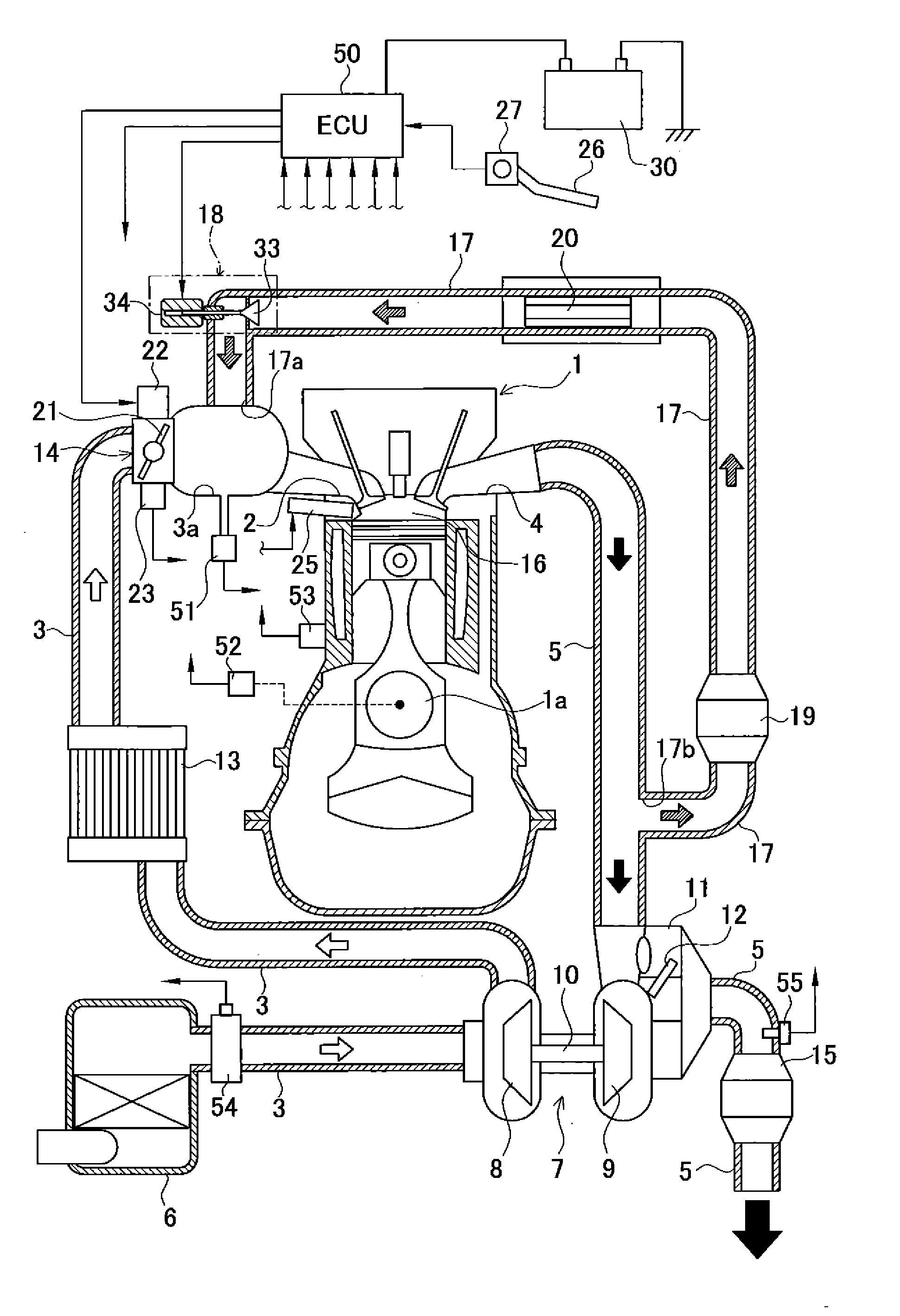
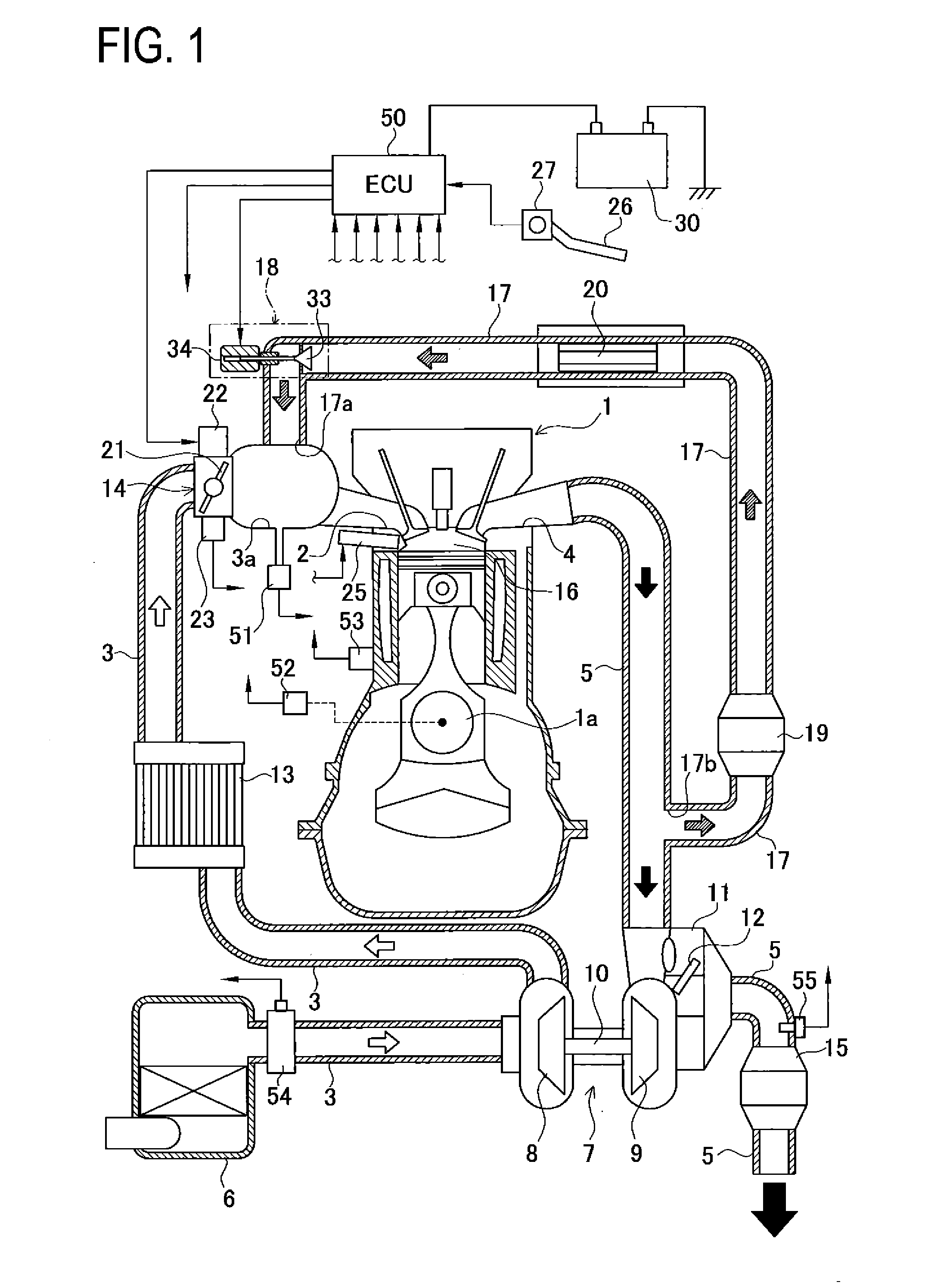
[0026]FIG. 1 is a schematic configuration view of a supercharger-equipped engine system including an exhaust gas recirculation (EGR) apparatus for an engine in the present embodiment. This engine system includes a reciprocating-type engine 1. This engine 1 has an intake port 2 connected to an intake passage 3 and an exhaust port 4 connected to an exhaust passage 5. An air cleaner 6 is provided at an inlet of the intake passage 3. In the intake passage 3 downstream from the air cleaner 6, a supercharger 7 is placed in a position between a portion of the intake passage 3 and a portion of the exhaust passage 5 to increase the pressure of intake air in the intake passage 3.
[0027]The supercharger 7 includes a compressor 8 placed in the intake passage 3, a turbine 9 placed in the exhaus...
second embodiment
[0061]A second embodiment of an exhaust gas recirculation for an engine according to the invention will be described below referring to the accompanied drawings.
[0062]In the following explanation, similar or identical parts to those in the first embodiment are assigned the same reference signs and their details are not repeated. The following explanation is thus given with a focus on differences from the first embodiment.
[0063]This second embodiment differs from the first embodiment in the processing details of the EGR valve opening control routine. FM 7 is a flowchart showing one example of the processing details of the EGR valve opening control routine to be executed by the ECU 50 in the present embodiment.
[0064]The flowchart in FIG. 7 is different from the flowchart in FIG. 4 in the processing details in Steps 300, 310, and 320. The processing details in the remaining Steps 200 to 250, 270, and 280 in FIG. 7 are the same as those in the flowchart in FIG. 4.
[0065]As shown in FIG. ...
third embodiment
[0069]A third embodiment of an exhaust gas recirculation for an engine according to the invention will be described below referring to the accompanied drawings.
[0070]This third embodiment differs from the first and second embodiments in the processing details of the EGR valve opening control routine. FIG. 9 is a flowchart showing one example of the processing details of the EGR valve opening control routine to be executed by the ECU 50. In the third embodiment, the ECU 50 is one example of an energization control unit.
[0071]The flowchart in FIG. 9 is different from the flowchart in FIG. 4 in the processing details in Steps 400 to 460. The processing details in the remaining Steps 200 to 240 in FIG. 9 are the same as those in the flowchart in FIG. 4.
[0072]As shown in FIG. 9, in Step 400 following Step 240, the ECU 50 judges whether or not the target opening degree Tegr of the EGR valve 18 is larger than “0”. Specifically, the ECU 50 judges whether or not a request to open the EGR val...
PUM
 Abstract
Description
Claims
Application Information
 - R&D
- Intellectual Property
- Life Sciences
- Materials
- Tech Scout
- Unparalleled Data Quality
- Higher Quality Content
- 60% Fewer Hallucinations
Browse by: Latest US Patents, China's latest patents, Technical Efficacy Thesaurus, Application Domain, Technology Topic, Popular Technical Reports.
© 2025 PatSnap. All rights reserved.Legal|Privacy policy|Modern Slavery Act Transparency Statement|Sitemap|About US| Contact US: help@patsnap.com