
Efficient Energy Use in Low Power Products

a low-power product and energy-saving technology, applied in the direction of electric variable regulation, process and machine control, instruments, etc., can solve the problems of reducing the physical dimensions of the device, and the conversion efficiency in the discontinuous mode falling off, so as to reduce the total current consumption and switch efficiency gains

Active Publication Date: 2014-01-16
XUESHAN TECH INC
View PDF4 Cites 5 Cited by
  • Summary
  • Abstract
  • Description
  • Claims
  • Application Information

AI Technical Summary

Benefits of technology

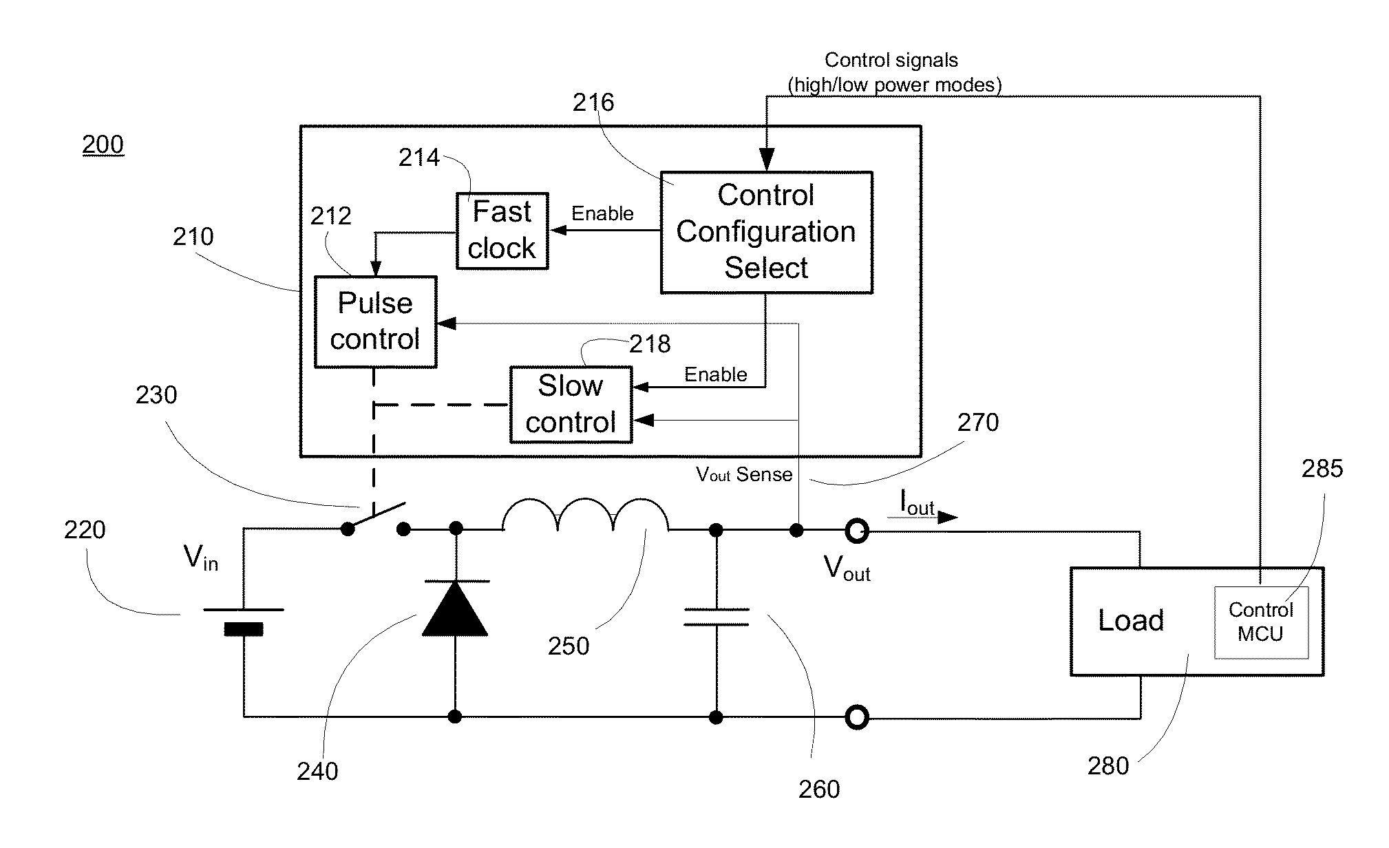
The patent text describes techniques that allow for more efficient switching in low power modes for products with sleep modes. This results in reduced current consumption and the removal of the need for a linear regulator. The techniques also allow for the use of switch mode conversion in both low and high power modes by adapting the operation of the switching regulator control circuitry in response to changes in the operating mode of the product. In low current modes, where current requirements are low and slowly changing, the rate at which energy pulses are required at the regulator output can be significantly reduced compared to the peak current case. This results in significantly extended time for the external capacitance to maintain the output voltage between defined voltage limits. It is also possible to relax ripple requirements in low current modes if sensitive analogue circuitry is not needed in such modes. This further improves efficiency by disabling unused portions of the high current control circuit in low current modes and ensuring that the low power control circuit design minimizes quiescent current between switching pulses.

Problems solved by technology

The increase in both the performance and portability of electronic devices creates challenges in that the underlying integrated circuits (ICs) require greater amounts of power to provide a greater degree of functionality and accuracy, while the physical dimensions of the devices are progressively reduced to improve portability.
The control circuit normally remains active so that it can respond to increased current demand when it occurs but constant energy losses in the control circuit mean that conversion efficiency in the discontinuous mode falls off as the output current is reduced.

Method used


Image

  • Efficient Energy Use in Low Power Products
  • Efficient Energy Use in Low Power Products
  • Efficient Energy Use in Low Power Products

Examples


Embodiment Construction

[0029]The example embodiment describes a switching regulator with control circuitry used for products that have a normal high power mode, but have sleep modes where activity is reduced to the absolute minimum. The sleep mode current is low and varies slowly, with ripple current requirements that are relaxed because no sensitive analogue circuits are active, for example, as in cellular phones. The control processor, control circuitry and main clock can be stopped, with only wakeup circuitry required to restore activity using a timed asynchronous interrupt.

[0030]Referring first to FIG. 1, a typical prior-art switching regulator and linear regulator combination is shown in simplified form at reference numeral 100, and comprises control circuitry 110, a power source (Vin) 120, switching and storage elements 130-160, output voltage (Vout) sensing 170, and a linear regulator 190, in this embodiment it is a low-dropout regulator (LDO). The output of the regulator 190 is applied to the load...


PUM


Abstract

Techniques are provided that can extend the efficiency of a switching regulator further into the low current region by making use of the available knowledge on predictable load variations and voltage ripple tolerance across different states, providing improved efficiency and reducing total current consumption. The load current requirement in low power states is provided using switch mode rather than linear regulation, the switch mode operation being controlled by a mode dependent control circuit so as to minimize the energy cost of the switching operation in each mode and thus obtain improved efficiency from the power source.

Description

FIELD OF THE INVENTION[0001]The present disclosure relates to the application of voltage regulator circuits and more particularly to improving the efficiency in low power modes, for products with sleep modes, thus reducing the total current consumption in battery powered devices.BACKGROUND OF THE INVENTION[0002]The increase in both the performance and portability of electronic devices creates challenges in that the underlying integrated circuits (ICs) require greater amounts of power to provide a greater degree of functionality and accuracy, while the physical dimensions of the devices are progressively reduced to improve portability.[0003]Voltage regulators are a particular type of circuit that is necessary for the functionality of portable electronic devices. They are used to convert a supply voltage from one value to a different value, typically from a high voltage to a lower voltage. A voltage regulator may be used to convert an input supply voltage to an operating voltage that ...

Claims


Application Information

Patent Timeline
Patent Type & Authority Applications(United States)
IPC IPC(8): G05F1/46
CPCH02M3/156Y02B70/10H02M1/0032G05F1/46G05F1/10
Inventor GEORGE-KELSO, SIMONBOIXADERA, FRANCESC
Owner XUESHAN TECH INC
Learn More