
Coating system for a gas turbine component

a gas turbine and component technology, applied in the direction of solid-state diffusion coating, superimposed coating process, machines/engines, etc., can solve the problems of earth disilicate ebcs, other components are exposed to mechanical, and vulnerable to sio leaching, so as to prolong the permeation of water vapor, prevent encroachment, and increase the useful life of cmc blades

Inactive Publication Date: 2014-01-09
GENERAL ELECTRIC CO
View PDF3 Cites 7 Cited by
  • Summary
  • Abstract
  • Description
  • Claims
  • Application Information

AI Technical Summary

Benefits of technology

The patent describes a coating system for turbine engine components made of ceramic matrix composites (CMCs). The system includes a protective coating called an environmental barrier coating (EBC) applied to the CMC substrate using a bond coat. The coating prevents water vapor and oxygen from entering the EBC layers, which can cause damage to the components. By increasing the life of the CMC blades, the coating system can save money, be more reliable, and have a longer useful life.

Problems solved by technology

In addition to thermal stresses, these and other components are also exposed to mechanical stresses, loads, and erosion from particles in the hot gases that further wear on the components.
RE disilicates have a general composition of RE2Si2O7, and RE monosilicates have a general composition of RE2SiO5 A drawback of the rare earth disilicate EBCs is that they are vulnerable to leaching of SiO2 which creates a microporous microstructure in the EBC, and an initially dense EBC is converted to a porous layer in less than the required design lifetime.
Thus, such disilicates may not have the durability required for the application.
Rare earth monosilicates typically have CTEs that are not well matched to the CTE of the CMC substrate material.
As a result, the monosilicate topcoats tend to crack during application, heat treatment and / or service exposure, allowing water vapor to penetrate the topcoat and cause subsurface chemical reactions and / or premature EBC spallation.
Prior solutions failed to take into account the directional deposition of Si for improved adhesion and greater oxidation protection.

Method used


Image

  • Coating system for a gas turbine component
  • Coating system for a gas turbine component
  • Coating system for a gas turbine component

Examples


Embodiment Construction

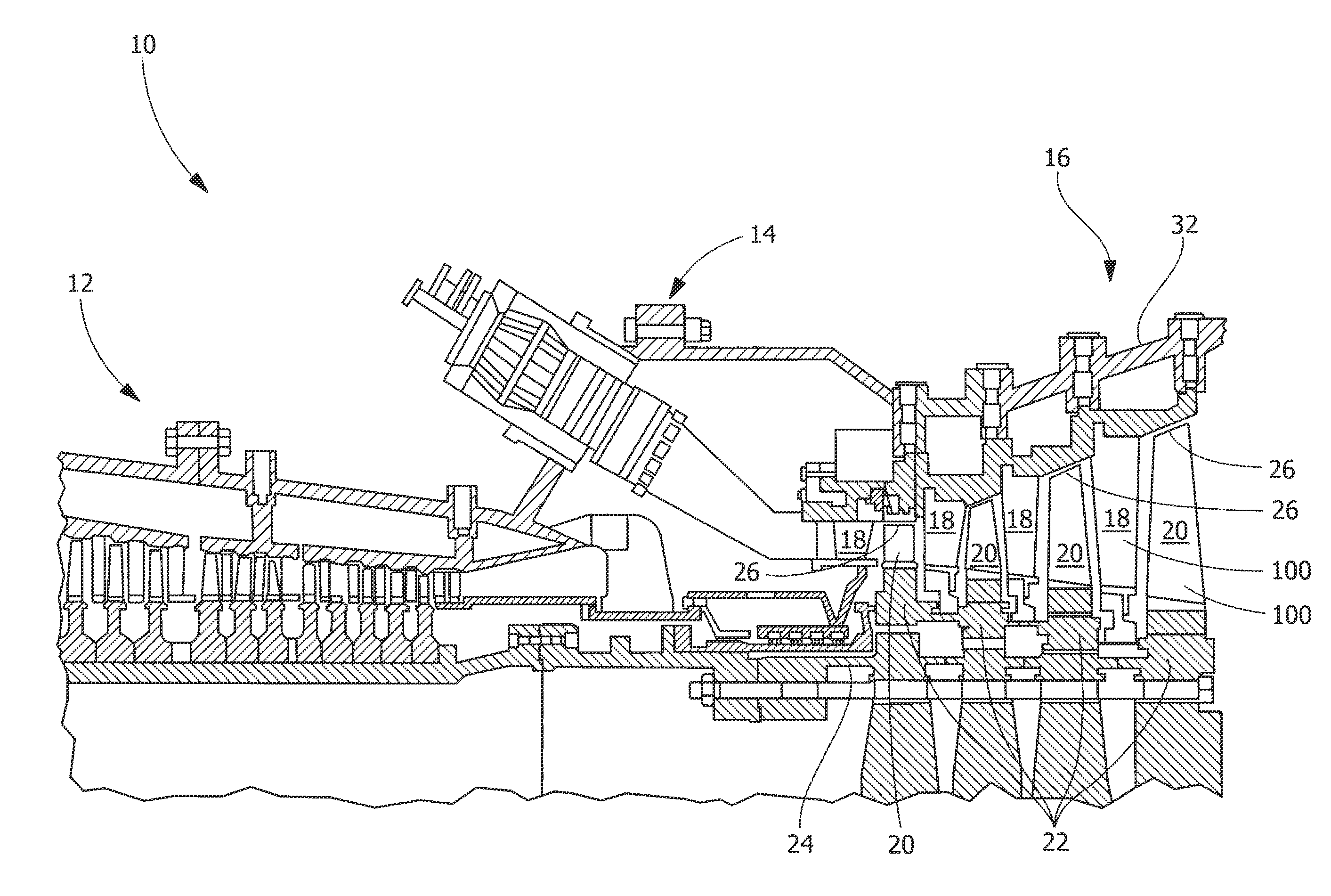
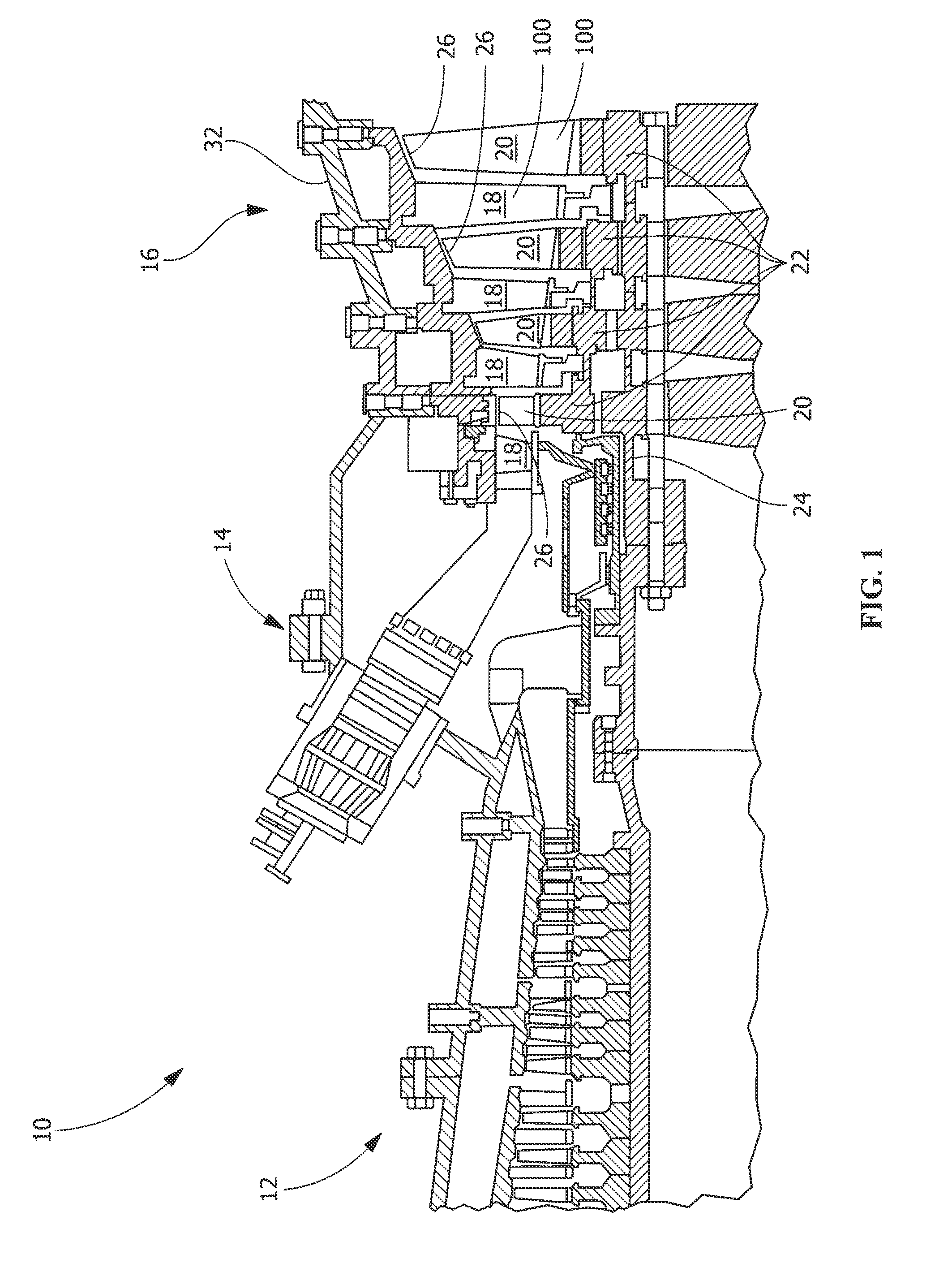
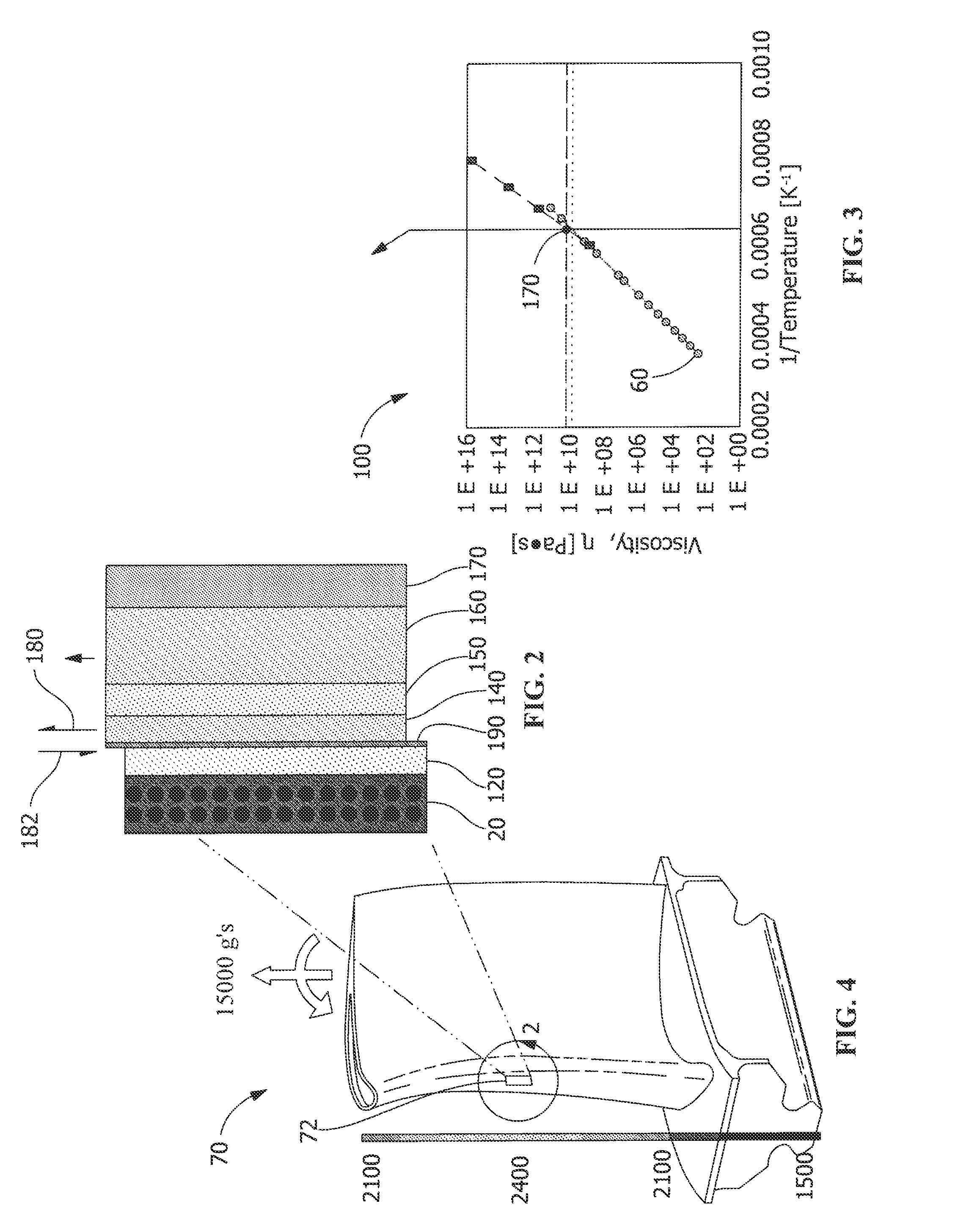
[0023]One or more specific embodiments of the present invention will be described below. In an effort to provide a concise description of these embodiments, all features of an actual implementation may not be described in the specification. It should be appreciated that in the development of any such actual implementation, as in any engineering or design project, numerous implementation-specific decisions must be made to achieve the developers' specific goals, such as compliance with system-related and business-related constraints, which may vary from one implementation to another. Moreover, it should be appreciated that such a development effort might be complex and time consuming, but would nevertheless be a routine undertaking of design, fabrication, and manufacture for those of ordinary skill having the benefit of this disclosure.

[0024]When introducing elements of various embodiments of the present invention, the articles “a,”“an,”“the,” and “said” are intended to mean that ther...


PUM

PropertyMeasurementUnit
firing temperaturesaaaaaaaaaa
operational temperaturesaaaaaaaaaa
temperatureaaaaaaaaaa

Abstract

A system or method for applying a protective environmental coating for a gas turbine component. The coating includes a bond layer applied to a substrate comprised of a ceramic matrix composite material and environmental barrier coating layers. The first environmental barrier coating layer is bonded to the substrate by the bond layer. The bond layer comprises silicon and particles consisting of particles of Lanthanum or Cerium.

Description

FIELD OF THE INVENTION[0001]The application generally relates to a composition for protection of an environmental barrier coating (EBC) on ceramic matrix composition substrates. The application relates more specifically to a compositional coating for protection of EBC on a substrate formed of ceramic matrix composites (CMC).BACKGROUND OF THE INVENTION[0002]Power generation systems, such as gas turbine engines, steam turbines, and other turbine assemblies include a compressor section for supplying a flow of compressed combustion air, a combustor section for burning fuel in the compressed combustion air, and a turbine section for extracting thermal energy from the combustion air and converting that energy into mechanical energy in the form of a rotating shaft.[0003]Modern high efficiency combustion turbines have firing temperatures that exceed about 1,000° C., and even higher firing temperatures are expected as the demand for more efficient engines continues. Many components that form...

Claims


Application Information

Patent Timeline
Patent Type & Authority Applications(United States)
IPC IPC(8): B32B9/04C23C16/48C23C4/12B05D3/02C23C16/44
CPCC23C28/042C23C28/044C23C30/00F01D5/288C04B41/009C04B41/52C04B41/89F05D2300/6033C04B35/565C04B35/806C04B35/584C04B41/5096C04B41/515C04B41/4558C04B41/5035C04B41/5024C04B2103/0021C04B2103/001C04B41/524C04B41/526C04B35/80
Inventor DAS, RUPAKSCHAEFFER, JON CONRADZHANG, JAMES
Owner GENERAL ELECTRIC CO
Learn More