
Solenoid valve with flat core and flat spring

Inactive Publication Date: 2014-01-09
ASCO JOUCOMATIC
View PDF8 Cites 26 Cited by
  • Summary
  • Abstract
  • Description
  • Claims
  • Application Information

AI Technical Summary

Benefits of technology

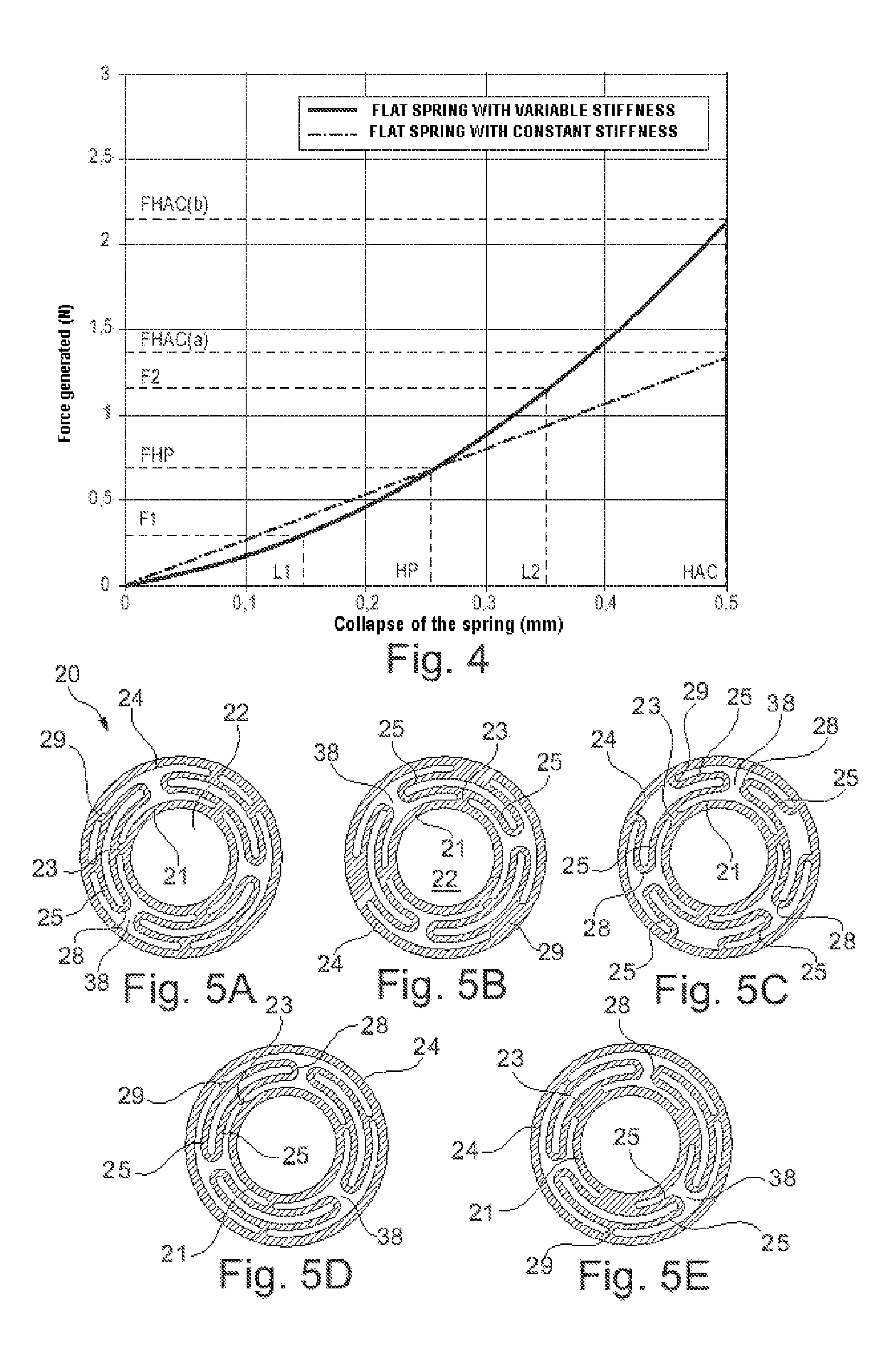
The present invention aims to improve solenoid valves by allowing them to handle higher leakage currents and use materials with high magnetic remanence without affecting their performance levels. The invention also benefits from a higher return force of the movable core after the coil is excited, even in the presence of residual power supply current and magnetic remanence. The separation of the twisting portions of the arms from the central and peripheral rings by cut-out portions prevents excessive stiffness of the spring and allows for deformation of the twist-flexible arms without exceeding maximum elongation during operation. The spring comprises portions that work by twisting and flexing, which provides good variability of stiffness and resistance to repeated deformations.

Problems solved by technology

This leakage current generally depends on the quality of the programmable logic controller used to control the solenoid valve, and a low tolerance of the solenoid valve to the leakage current demands the use of a more costly programmable logic controller with lower residual current.
It is not beneficial to counter the harmful effect of the leakage current and of the magnetic remanence by increasing simply the stiffness of the spring, because this increase then makes the separation of the valve gasket more difficult during the excitation of the coil and, in addition, the stresses exerted by the spring at rest depend on the manufacturing tolerances of the parts; the greater the stiffness of the spring, the greater the risk of the residual mechanical stresses after assembly being significant and prejudicial to the correct operation of the solenoid valve.
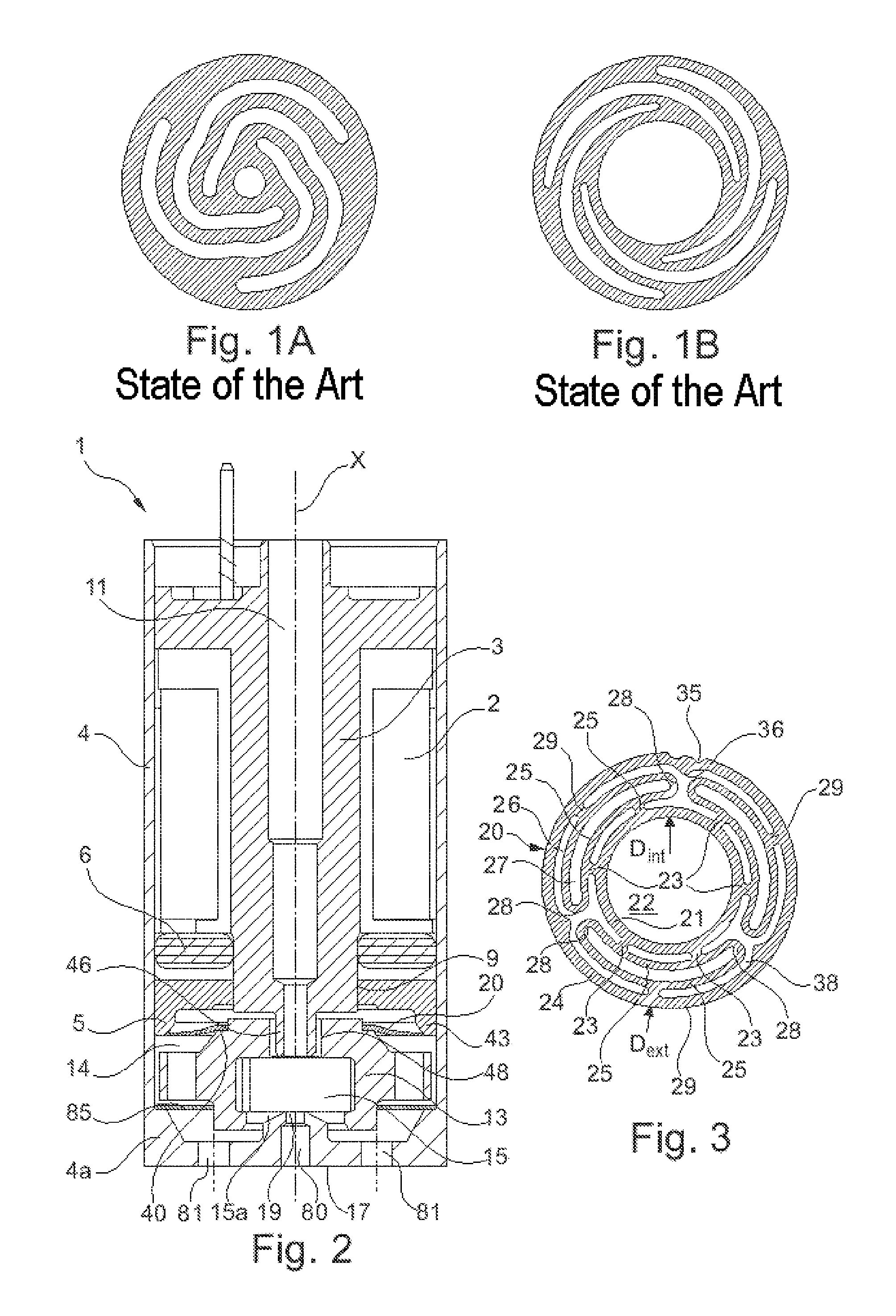
By contrast the known flat springs with variable stiffness used on solenoid valves with adjustable movable core are unsuited to use on solenoid valves with flat movable core, given the smaller difference in diameter between the central and peripheral rings.
Moreover, it is not easy to reduce the diameter of the portion of the movable core on which the flat spring is engaged, because such a reduction may reduce the expanse of ferromagnetic material of the movable core facing the fixed core and, correlatively, the attraction force exerted by the coil.
Furthermore, where a definition or use of a term in a reference, which is incorporated by reference herein, is inconsistent or contrary to the definition of that term provided herein, the definition of that term provided herein applies and the definition of that term in the reference does not apply.

Method used


Image

  • Solenoid valve with flat core and flat spring
  • Solenoid valve with flat core and flat spring
  • Solenoid valve with flat core and flat spring

Examples


Embodiment Construction

[0063]In the following detailed description of the preferred embodiments, reference is made to the accompanying drawings, which form a part thereof, and within which are shown by way of illustration specific embodiments by which the invention may be practiced. It is to be understood that other embodiments may be utilized and structural changes may be made without departing from the scope of the invention.

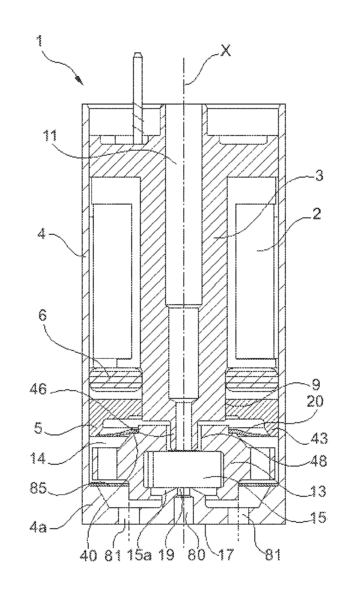
[0064]FIG. 2 shows an exemplary miniature solenoid valve according to the invention, conventionally comprising an electric coil 2, passed through by a fixed magnetic core 3 made of a ferromagnetic material, the assembly being for example housed as illustrated in a casing 4 extending longitudinally along an axis X, this casing 4 preferably also being made of a ferromagnetic material.

[0065]The solenoid valve 1 comprises a support ring 5 housed in the casing 4 and a seal gasket 6 arranged between the ring 5 and the coil 2 in the casing 4. This seal gasket 6 is applied on its greater di...


PUM


Abstract

A solenoid valve of the type with a flat core and a flat spring. The present invention related to a solenoid valve comprising a coil, a fixed core arranged inside the coil, a movable core arranged outside the coil, bearing a valve gasket, and a flat return spring to stress the movable core into a rest position, the solenoid valve being characterized in that the flat spring has variable stiffness, preferably bearing without embedding on corresponding surfaces of the solenoid valve.

Description

CROSS-REFERENCE TO RELATED APPLICATIONS[0001]This nonprovisional application is a continuation of and claims priority to French Application No. 1256485, entitled “Solenoid Valve of the Type with Flat Core and Flat Spring”, filed Jul. 5, 2012 by the same inventor.BACKGROUND OF THE INVENTION[0002]1. Field of the Invention[0003]This invention relates, generally, to solenoid valves. More specifically, it relates to pneumatic solenoid valves, notably those used with programmable logic controllers (PLC) to control a compressed air supply. In an embodiment, the invention notably addresses the so-called miniature solenoid valves, that is to say those that fit within a volume typically less than 20 cm3.[0004]2. Brief Description of the Prior Art[0005]A solenoid valve conventionally comprises a coil excited by an electrical current and an element that can move under the effect of the magnetic field generated when the coil is powered, this movable element bearing a valve gasket. A preloaded re...

Claims


Application Information

Patent Timeline
IPC IPC(8): F16K31/06
CPCF16K31/06F16F1/324F16K31/0627F16F1/027F16K31/0658
Inventor VANDAMME, RICHARD
Owner ASCO JOUCOMATIC
Learn More