Lamellar separator with catch basin

a technology of lamellar separator and catch basin, which is applied in the direction of colloidal chemistry, cleaning equipment, separation processes, etc., can solve the problems of reducing the efficiency of lamellar separator, etc., so as to reduce the harmful swirl of water level and upwardly-directed lateral flows in the lamellar space, the effect of improving the drainage of collected liquid

Active Publication Date: 2014-01-09
BALCKE DURR AG
View PDF1 Cites 5 Cited by
  • Summary
  • Abstract
  • Description
  • Claims
  • Application Information

AI Technical Summary

Benefits of technology

The invention is about a new design for a lamellar separator used in oil and gas production. The design includes a catch basin with multiple areas or chambers separated by partition walls. This prevents water droplets from being agitated and entrained by the fluid stream, which would reduce the efficiency of the separator. The separated liquid in the catch basin can be calmed and kept calm even at high flow speeds, reducing harmful swills and upwardly-directed lateral flows. The partition walls also improve drainage and help keep the level in the catch basin low. The technical effects of this design are improved performance, reduced energy consumption, and better overall operation of the lamellar separator.

Problems solved by technology

These lamellar separators known from the prior art are problematic in that the liquid located in the catch basin, in spite of a drain, is swirled and entrained by the fluid stream flowing through the lamellar separator or is spun upward into the lamellar separation space because of the swirling and entrained and discharged therefrom.
The immersion of the fluid flow into the catch basin and the accompanying upwardly-oriented lateral flows of the fluid stream from the catch basin into the lamellar space opposite to the drainage direction of the separated liquid droplets are also problematic, so that these droplets cannot drain downward unobstructed, but rather arc detached from the lamellar surface and expelled.
The geometric division of the catch basin into multiple areas or chambers using one or more partition walls prevents the water separated into the catch basin from being agitated and droplets from the agitated water surface from being entrained by the fluid stream flowing past and being carried back upward into the lamellar separation space, which would reduce the efficiency of the lamellar separator.

Method used


Image

  • Lamellar separator with catch basin
  • Lamellar separator with catch basin
  • Lamellar separator with catch basin

Examples


Embodiment Construction

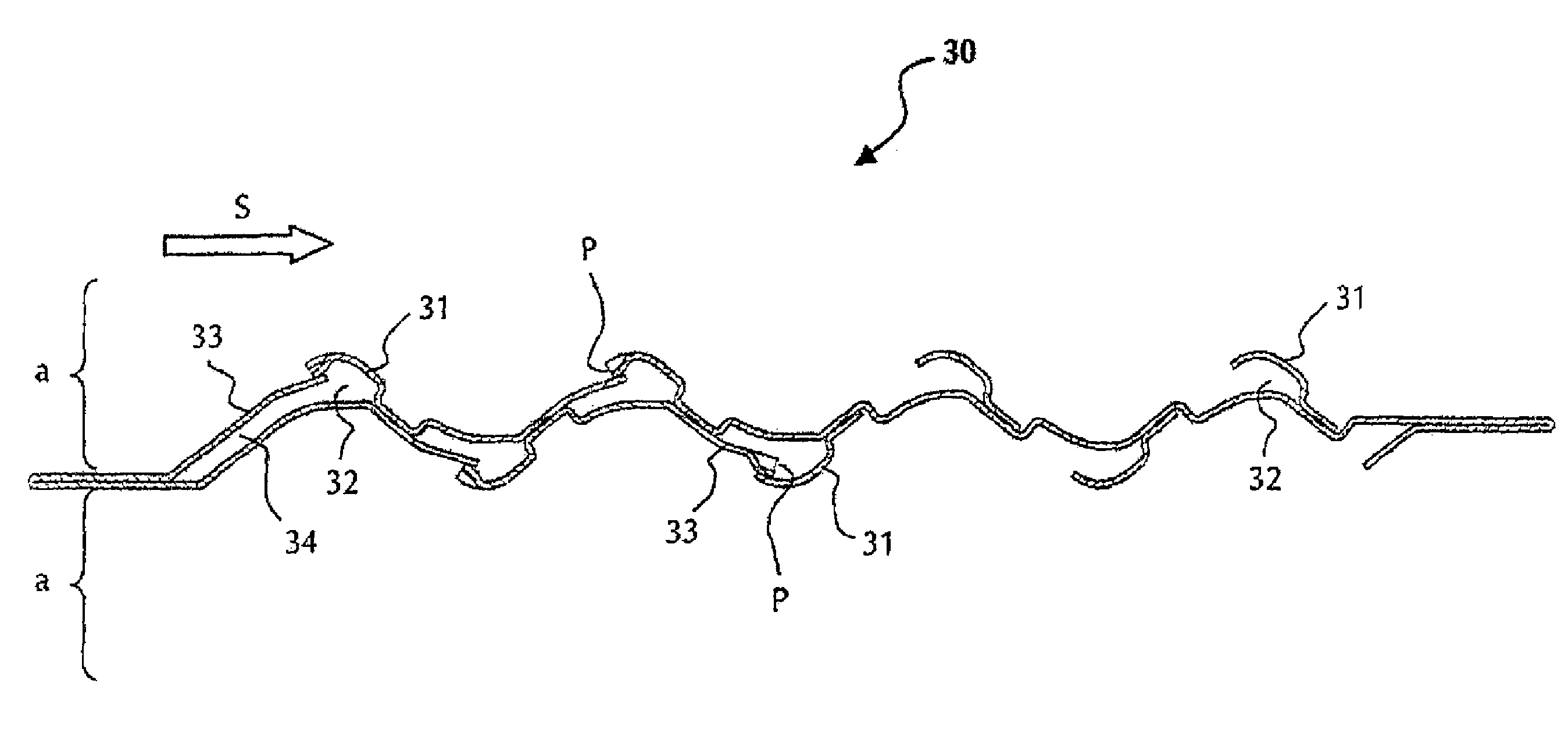
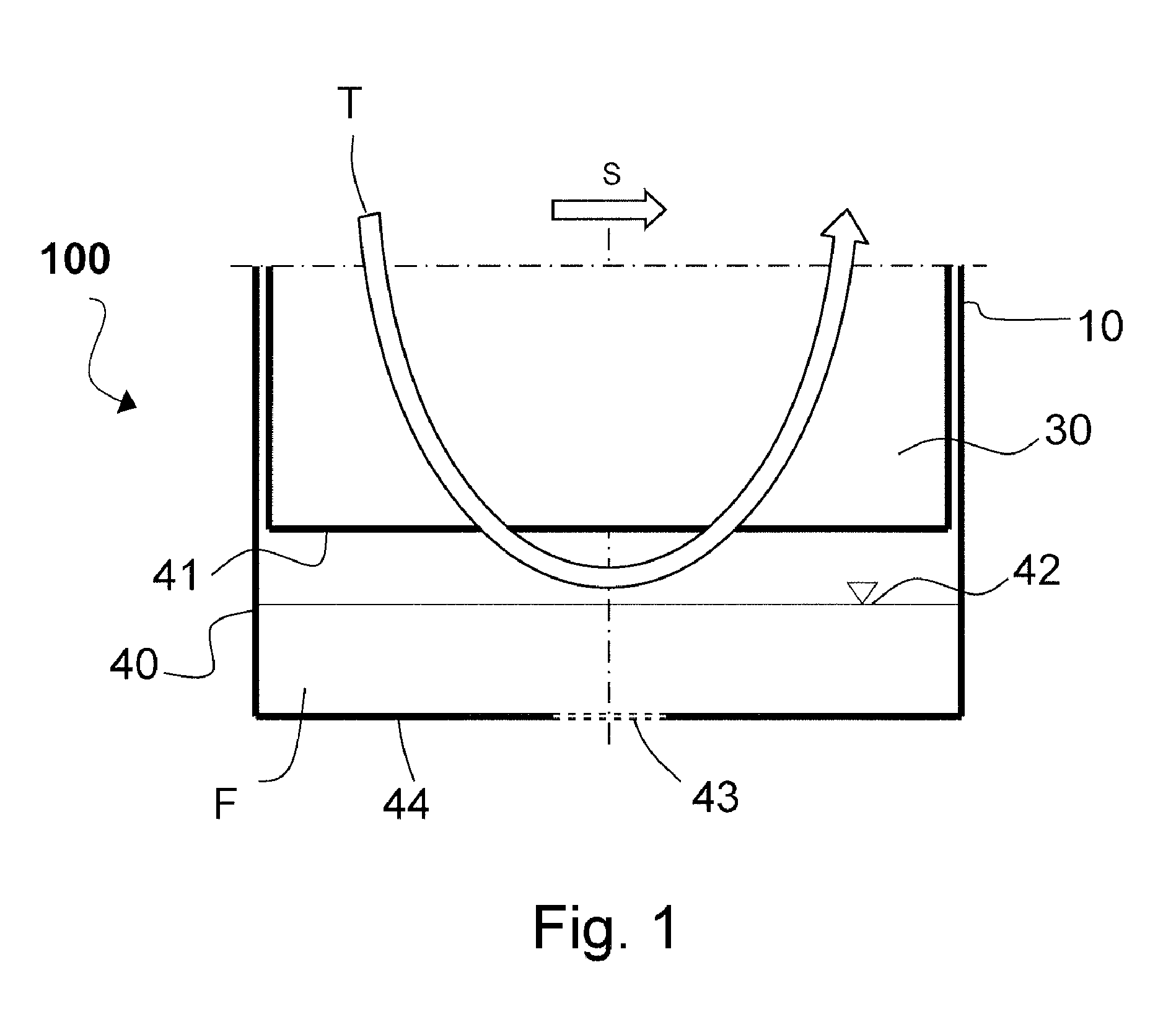
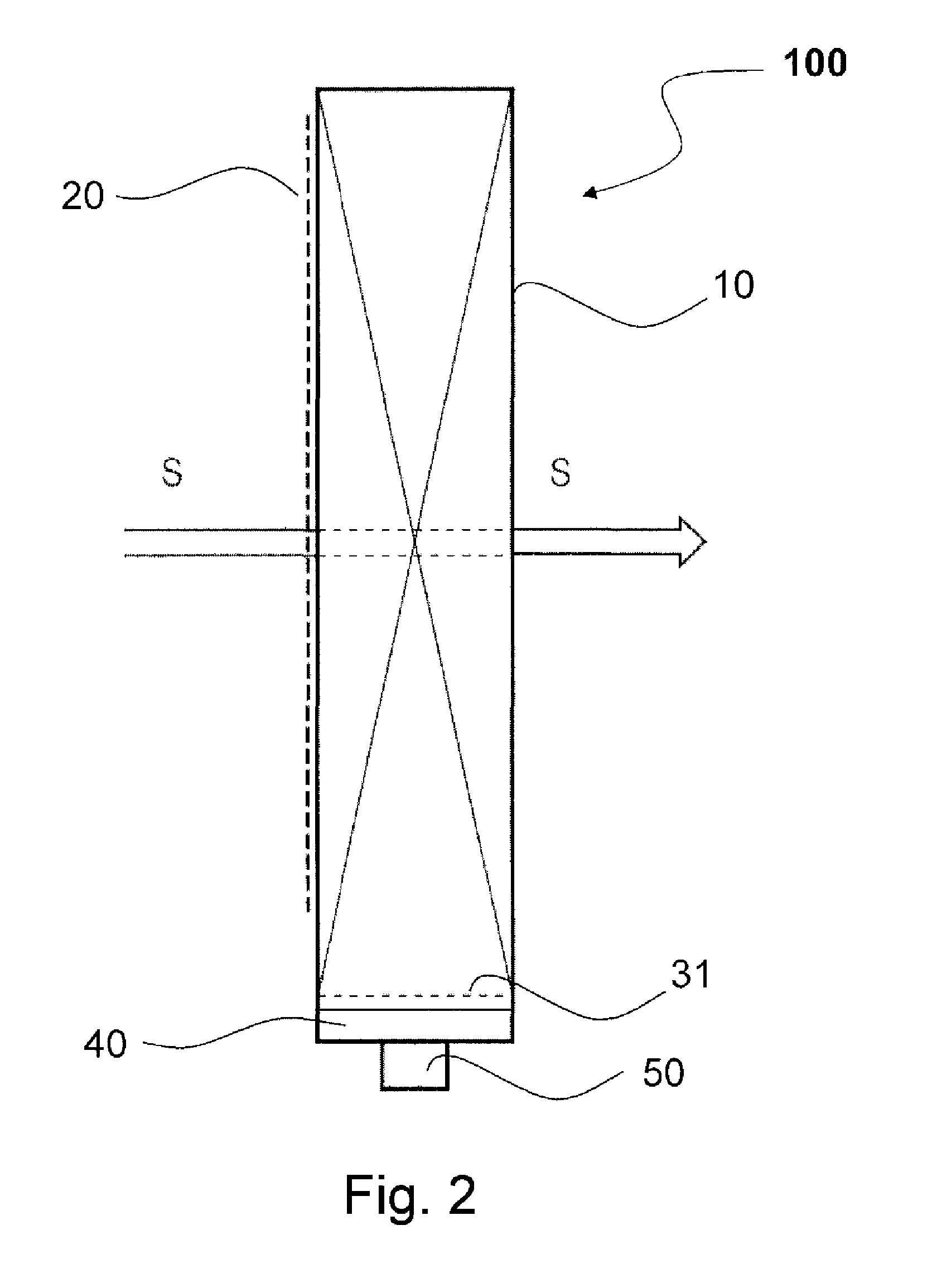
[0017]FIG. 1 illustrates a lower base area of a lamellar separator 100 according to the prior art. The lamellar separator 100 is enclosed by a housing 10, in which a catch basin 40 is integrated. The lamellar separator 100 has vertically oriented lamellar profiles situated in parallel and spaced apart from one another, which together form the lamellar separation space, of which only a lower part of a single lamellar profile 30 is visible in FIG. 1. A lower edge of the lamellar profile 30 is identified by 31. A liquid-charged fluid flows through the lamellar separator 100 in the specified through-flow direction S, liquid droplets being separated from the fluid flowing past on the wall surfaces of the lamellar profiles 30 in a known way. The separated liquid droplets agglomerate and drain downward because of gravity into the catch basin 40 provided for this purpose. The collected liquid F can drain through a drain opening 43 (illustrated by dashed lines) located in the basin floor 44....


PUM

PropertyMeasurementUnit
Flow rateaaaaaaaaaa
Areaaaaaaaaaaa

Abstract

The invention relates to a lamellar separator for separating liquid droplets from a liquid-charged fluid, having at least two essentially vertically oriented lamellar profiles, which are spaced apart from one another, and which form a flow channel between them for conducting through the liquid-charged fluid and on the wall surfaces of which the liquid droplets are separated, and having a catch basin situated below the lamellar profiles for receiving the liquid separated from the liquid-charged fluid, the catch basin having at least one partition wall, which divides the catch basin into multiple areas.

Description

FIELD OF THE INVENTION[0001]The invention relates to a lamellar separator for separating liquid droplets from a liquid-charged fluid, having at least two essentially vertically oriented lamellar profiles, which are spaced apart from one another, and which form a flow channel for conducting through the liquid-charged fluid between them and on the wall surfaces of which the liquid droplets are separated, and having a catch basin situated at the lower end of the lamellar profiles for receiving the liquid separated from the liquid-charged fluid.BACKGROUND OF THE INVENTION[0002]Such lamellar separators, which are also referred to as lamellar droplet separators, are known from the prior art and are used in various processes for separating liquid droplets from a liquid-charged fluid, in particular a gas flow. In power plants, such as solar or atomic power plants, effective separation of droplets from the wet steam decides the thermal efficiency of the plant. During the intermediate superhe...

Claims


Application Information

Patent Timeline
IPC IPC(8): B01D49/00
CPCB01D45/04A47L9/1608A47L9/1683B01D45/16B01D46/0031Y10S55/03
Inventor BONATI, GUIDOSTUCKENSCHNEIDER, GERDSTAHLHUT, JORG
Owner BALCKE DURR AG
Why Eureka
Try Eureka