
Oral/nasal cannula manifold

a cannula and manifold technology, applied in the field of oral/nasal cannula manifolds, can solve the problems of reducing the accuracy of the analysis of the sample by the gas analyzer, reducing the amount of information obtained from the analysis, and undesirable diminished fidelity of the gas sampling flow dynamics, so as to improve the accuracy of the oral/nasal sampling manifold, enhance the performance of the oral collection portal, and improve the accuracy of the oral/nasal

Inactive Publication Date: 2014-01-02
DERRICK STEVEN J
View PDF2 Cites 20 Cited by
  • Summary
  • Abstract
  • Description
  • Claims
  • Application Information

AI Technical Summary

Benefits of technology

The present invention is an oral / nasal sampling manifold that ensures effective analysis of a person's exhaled gases by aligning the nasal and oral passages with the conduit passage of the suction port without any adjacent connected dead or void volumes and without any curvatures in the respective passages. The oral collection portal is also improved by providing a deflector concentrator plate. The oral / nasal manifold is formed of a flame retardant thermoplastic polymer to reduce the hazzard of fire sometimes experienced with the use of supplemental oxygen administration.

Problems solved by technology

As the gas mixtures travel from the patient to the gas analyzer, the concentration of the gases can be effected by mixing of the component gases, which reduces the accuracy of the analysis of the sample by the gas analyzer, and reduces the amount of information obtained from the analysis.
The deficiency in these prior art designs is the undesirable diminished fidelity resulting from gas sampling flow dynamics.
Specifically, the amount of curvature in the cannula passages and the amount of dead or void space gases, which have limited or no carbon dioxide content, that is analyzed along with the actual ventilatory gases, results in a diluted sample which produces a lesser quality or low fidelity signal generation.

Method used


Image

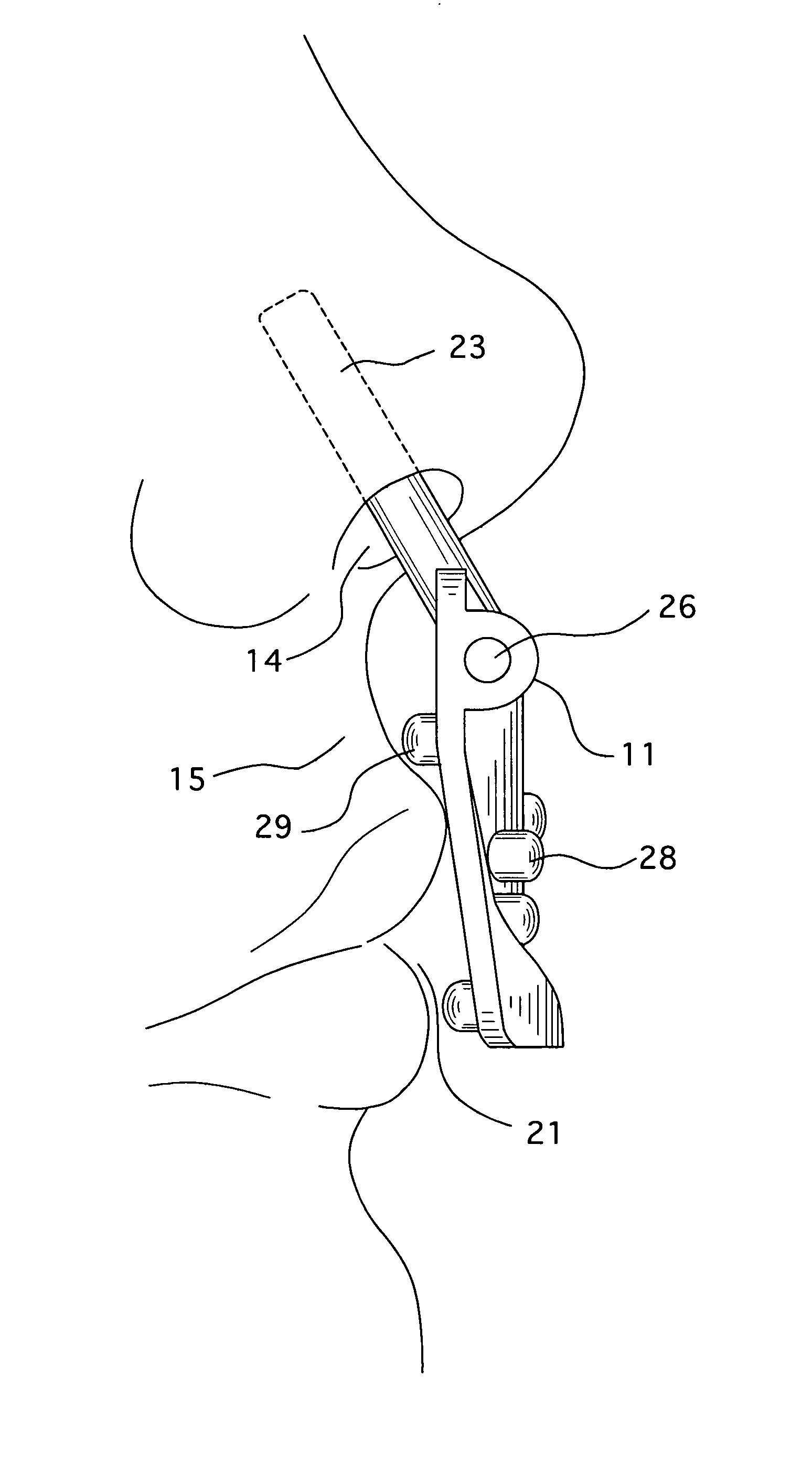
  • Oral/nasal cannula manifold
  • Oral/nasal cannula manifold
  • Oral/nasal cannula manifold

Examples


Embodiment Construction

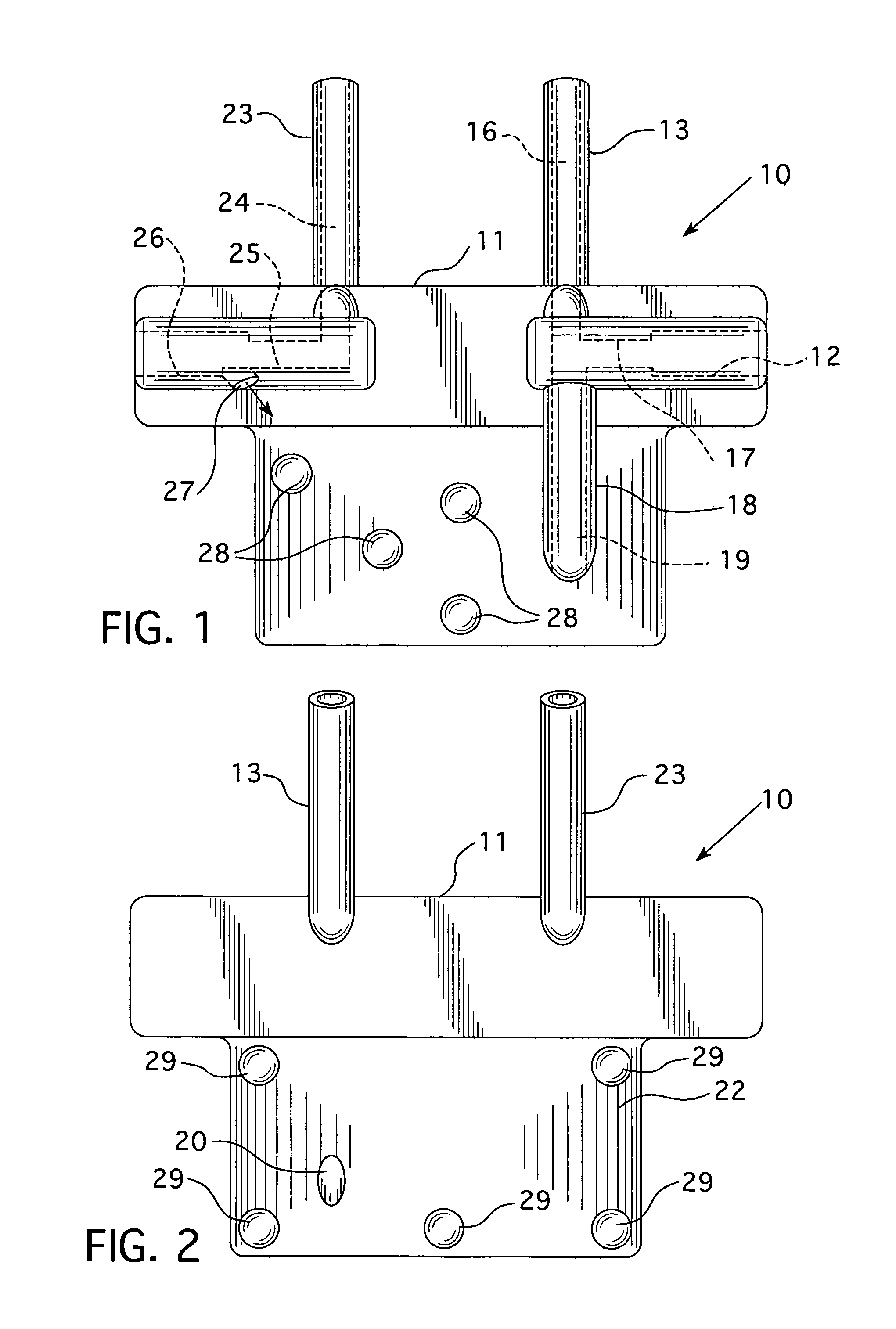
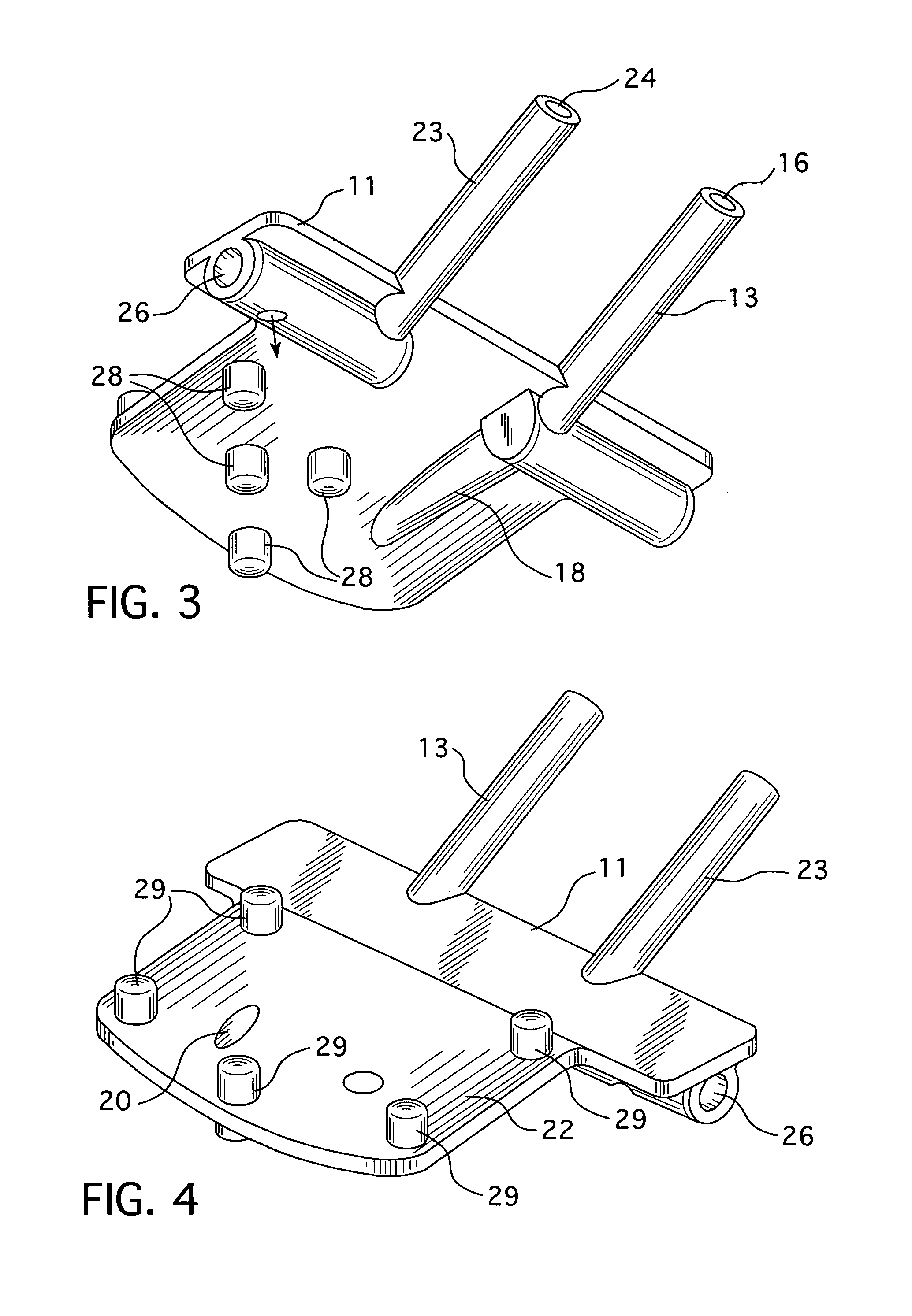
[0021]Referring to the drawings, oral / nasal cannula manifold 10 of the present invention is provided for sampling exhaled breath of a subject and includes a main body portion 11 having formed therein a suction port 12 (FIG. 1) which is dimensioned and adapted to be connected with a collection tube (not shown) to a suction device (not shown) for sampling of exhaled breath of the subject known as a capnographic analyzer in the industry for determining the respired CO2 content.

[0022]A nasal prong 13 protrudes upwardly from main body portion 11 and is positioned for insertion into a nostril (similar to that as shown at 14 in FIG. 7) to collect nasally exhaled breath of the subject 15. Nasal prong 13 is provided with an internal straight passage 16 which is in fluid flow communication with conduit passage 17 of suction port 12.

[0023]Oral prong 18 is directed downwardly through the main body portion 11 and is also provided with a straight conduit passage 19 having a distal opening 20 for ...


PUM


Abstract

An oral / nasal cannula manifold gas sampling and oxygen delivering manifold for sampling exhaled breath of a subject and delivering supplemental oxygen, the cannula including a main body portion having a suction port which is connected with a collection tube to a suction device for sampling the exhaled breath of the subject. A nasal prong upwardly protrudes from the main body portion and is positioned for insertion into a nostril of the subject to collect nasally exhaled breath. An oral conduit passage is embedded in a deflector / concentrator plate that extends downwardly from the main body portion. The straight conduit passages of the nasal and oral passages are connected to and aligned in the same plane whereby the opposed nasal and oral conduit passages are connected with the conduit passage of the suction port without any adjacent connected void volumes or dead spaces in any of the passages.

Description

FIELD OF THE INVENTION[0001]The present invention relates to the field of oral / nasal cannula manifold for use in sampling breath of subjects, especially for the purpose of providing capnographic data concerning the subject.BACKGROUND OF THE INVENTION[0002]During anesthesia, and especially during sedation anesthesia or patient controlled analgesia it is often desirable to collect and analyze qualitatively and quantitatively the constituents of gases respired by the patient.[0003]Oral / nasal cannula manifolds are used to deliver supplemental oxygen to hospital patients who require respiratory support and to collect carbon dioxide samples from the patients to monitor respiration. The oral / nasal manifold is configured to be in close proximity to the oral cavity and also inserted into the nasal cavity of the patient. The patient's exhaled breath is drawn through the manifold passages to a gas analyzer to be analyzed. The results of this analysis provides an indication of respiratory adequ...

Claims


Application Information

Patent Timeline
IPC IPC(8): A61B5/097A61M16/00
CPCA61B5/097A61B5/082A61B5/0836A61B5/4821A61B2560/04A61M16/0666A61M16/0672A61M16/085A61M16/1005A61M2230/432
Inventor DERRICK, STEVEN J.
Owner DERRICK STEVEN J
Learn More