Accelerated magnetic resonance thermometry

a magnetic resonance thermometer and accelerated technology, applied in the field of magnetic resonance imaging, can solve the problems of not giving absolute temperature, and the method is too slow to be used in continuous imaging for most applications

Active Publication Date: 2014-01-02
KONINKLIJKE PHILIPS ELECTRONICS NV
View PDF20 Cites 11 Cited by
  • Summary
  • Abstract
  • Description
  • Claims
  • Application Information

AI Technical Summary

Benefits of technology

[0035]Execution of the instructions further cause the processor to re-calculate the calibration thermal map using the spectroscopic magnetic resonance data. Execution of the instructions further cause the processor to re-acquire the baseline magnetic resonance thermometry data. This embodiment is particularly advantageous because over an extended period of time the temperature map may become increasingly inaccurate. Essentially anything which affects the magnetic resonance measurements may do this. For instance there may be B0 drift in the magnetic field, the gradient fields may heat and may change the magnetic field that they generate, and there may also be other components which heat or change during the process which cause a change in the magnetic resonance thermometry data that is unrelated to a temperature change within the subject. This embodiment is particularly advantageous when performing PRF thermometry over multiple consecutive heatin...

Problems solved by technology

The weakness of the method is that it does not give absolute temperature, but the temperature change relative to a certain, supposedly known initial state.
Another method, the proton ...

Method used


Image

  • Accelerated magnetic resonance thermometry
  • Accelerated magnetic resonance thermometry
  • Accelerated magnetic resonance thermometry

Examples


Embodiment Construction

[0071]Like numbered elements in these figures are either equivalent elements or perform the same function. Elements which have been discussed previously will not necessarily be discussed in later figures if the function is equivalent.

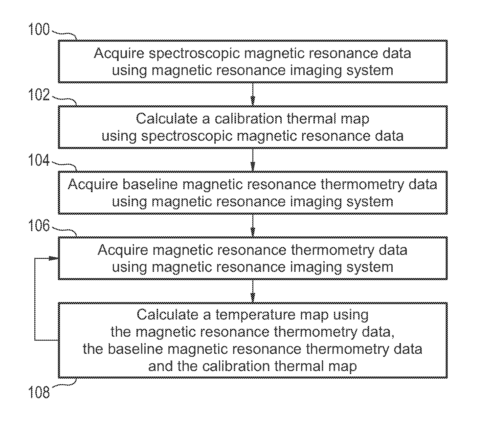
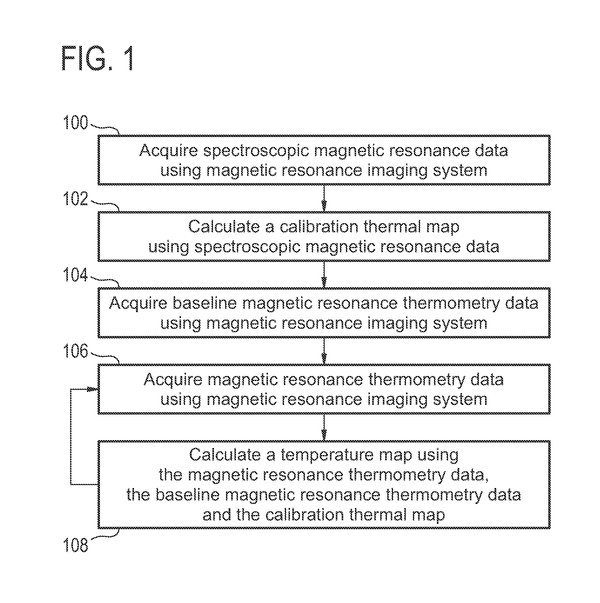
[0072]FIG. 1 shows a flow diagram which illustrates a method according to an embodiment of the invention. First in step 100 spectroscopic magnetic resonance data is acquired using a magnetic resonance imaging system. In step 102 a calibration thermal map is calculated using the spectroscopic magnetic resonance data. In step 104 baseline magnetic resonance thermometry data is acquired using the magnetic resonance imaging system. The baseline magnetic resonance thermometry data may be used to create a baseline set of measurements for comparison to the calibration thermal map. Next in step 106 magnetic resonance thermometry data is acquired using the magnetic resonance imaging system. In step 108 a temperature map is calculated using the magnetic resonance...


PUM


Abstract

A medical apparatus (300, 400, 500, 600) comprising a magnetic resonance imaging system (302). The medical apparatus further comprises a memory (332) storing machine readable instructions (352, 354, 356, 358, 470, 472, 474) for execution by a processor (326). Execution of the instructions causes the processor to acquire (100, 202) spectroscopic magnetic resonance data (334). Execution of the instructions further cause the processor to calculate (102, 204) a calibration thermal map (336) using the spectroscopic magnetic resonance data. Execution of the instructions further causes the processor to acquire (104, 206) baseline magnetic resonance thermometry data (338). Execution of the instructions further causes the processor to repeatedly acquire (106, 212) magnetic resonance thermometry data (340). Execution of the instructions further cause the processor to calculate (108, 214) a temperature map (351) using the magnetic resonance thermometry data, the calibration thermal map, and the baseline magnetic resonance thermometry data.

Description

TECHNICAL FIELD[0001]The invention relates to magnetic resonance imaging, in particular the measurement of temperatures using magnetic resonance imaging.BACKGROUND OF THE INVENTION[0002]In recent years magnetic resonance thermometry has been coupled with various means of heating or cooling tissue for therapy. Measuring the effect of the tissue heating or cooling allows the guiding of the therapy and also the ability to assess the effect of a therapeutic treatment on a subject.[0003]In high-intensity focused ultrasound (HIFU) therapy, reliable real-time temperature monitoring using e.g. Magnetic Resonance Imaging (MRI) is necessary to ensure a sufficient thermal necrosis to the target while avoiding excessive heating and damage of surrounding healthy tissues. To achieve sufficient temporal and spatial resolution, fast imaging is required preferably with a high spatial resolution while maintaining a sufficient SNR for reconstruction of reliable temperature measurements.[0004]In Rieke ...

Claims


Application Information

Patent Timeline
IPC IPC(8): G01R33/48A61B5/055
CPCG01R33/4804A61B5/055A61B18/02A61B18/12A61B18/1815A61B18/20A61B2017/00084A61B2018/00791A61B2090/374A61N7/02A61N2007/0065G01R33/4808G01R33/4814
Inventor KOHLER, MAX OSKARVAHALA, ERKKI TAPANINURMILAUKAS, KIRSI ILONA
Owner KONINKLIJKE PHILIPS ELECTRONICS NV
Why Eureka
Try Eureka