
Free form custom lens design manufacturing apparatus, system and business method

a manufacturing apparatus and lens technology, applied in the field of vision correction, can solve the problems of not being able to correct all refractive errors, many visual defects, and commonly known as aberrations

Inactive Publication Date: 2014-01-02
JOHNSON & JOHNSON VISION CARE INC
View PDF12 Cites 12 Cited by
  • Summary
  • Abstract
  • Description
  • Claims
  • Application Information

AI Technical Summary

Benefits of technology

The patent describes a method and system for custom lens manufacturing for vision correction. The method includes obtaining data measurements from a patient's eye, either bare eye, habitual lens or fitting lens, and transmitting the data to a computer system for analysis and design. The analysis includes comparing the data to a database of preset options and providing a display for the patient to make a selection based on their subjective evaluation of better vision. The computer system then generates a custom lens design based on the selected options. The resulting custom lens has improved vision compared to traditional methods and can be made using a free form custom lens manufacturing system.

Problems solved by technology

Many visual defects, also commonly known as aberrations, may arise from refractive abnormalities that have an adverse impact on imaging properties of an eye.
While spectacles, contact lenses, and the like generally help people see better, they do not and cannot correct all refractive error.
For example, although many lens products on the market today correct for some of the more commonly known low to mid order aberrations such as myopia, hyperopia, and astigmatism, they do not address higher order aberration vision correction such as coma, trefoil, and higher order sphere due to current manufacturing process limitations.
However, such treatment may put the patient at risk and often can lead to other visual limitations such as glare, reduced nighttime vision, dry eye and myopia.
Lenses derived from laser ablation are limited in that an increase in the cuts that have to be made to obtain a desired shape results in a decrease in the optical quality of the lens.
Lathing is time consuming and lenses derived from lathing are limited to the scope of the surface available.
Lenses derived from cast-molding are limited to the design of the mold utilized.

Method used


Image

  • Free form custom lens design manufacturing apparatus, system and business method
  • Free form custom lens design manufacturing apparatus, system and business method
  • Free form custom lens design manufacturing apparatus, system and business method

Examples


examples

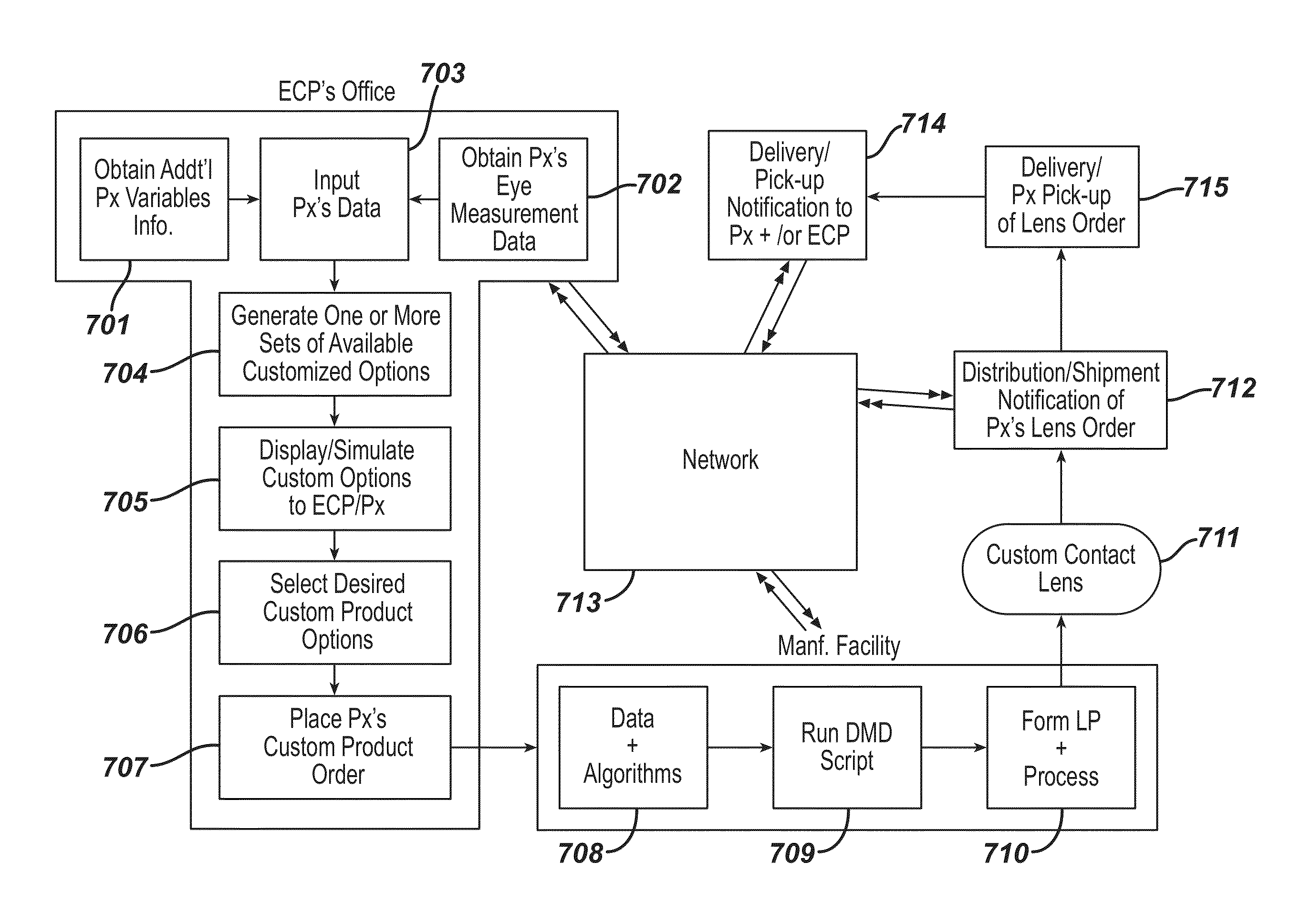
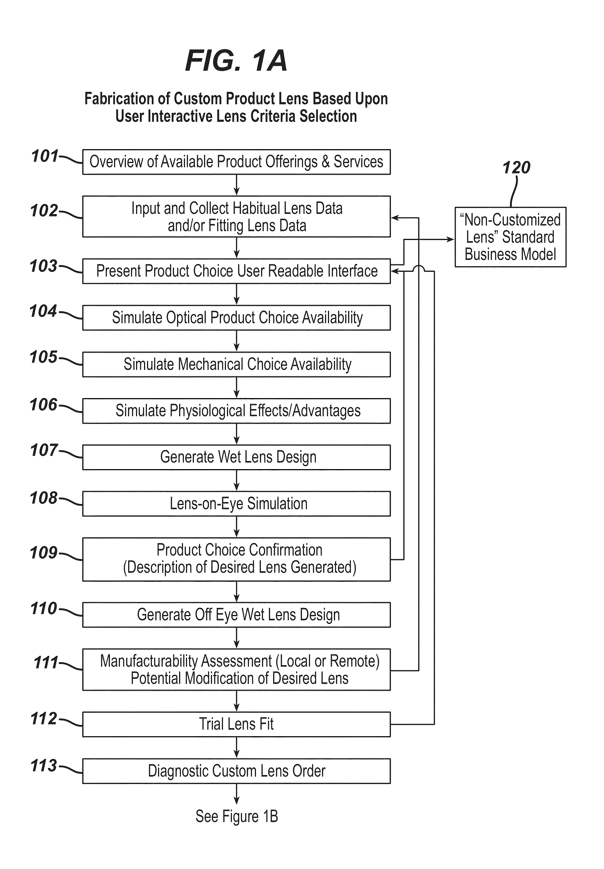
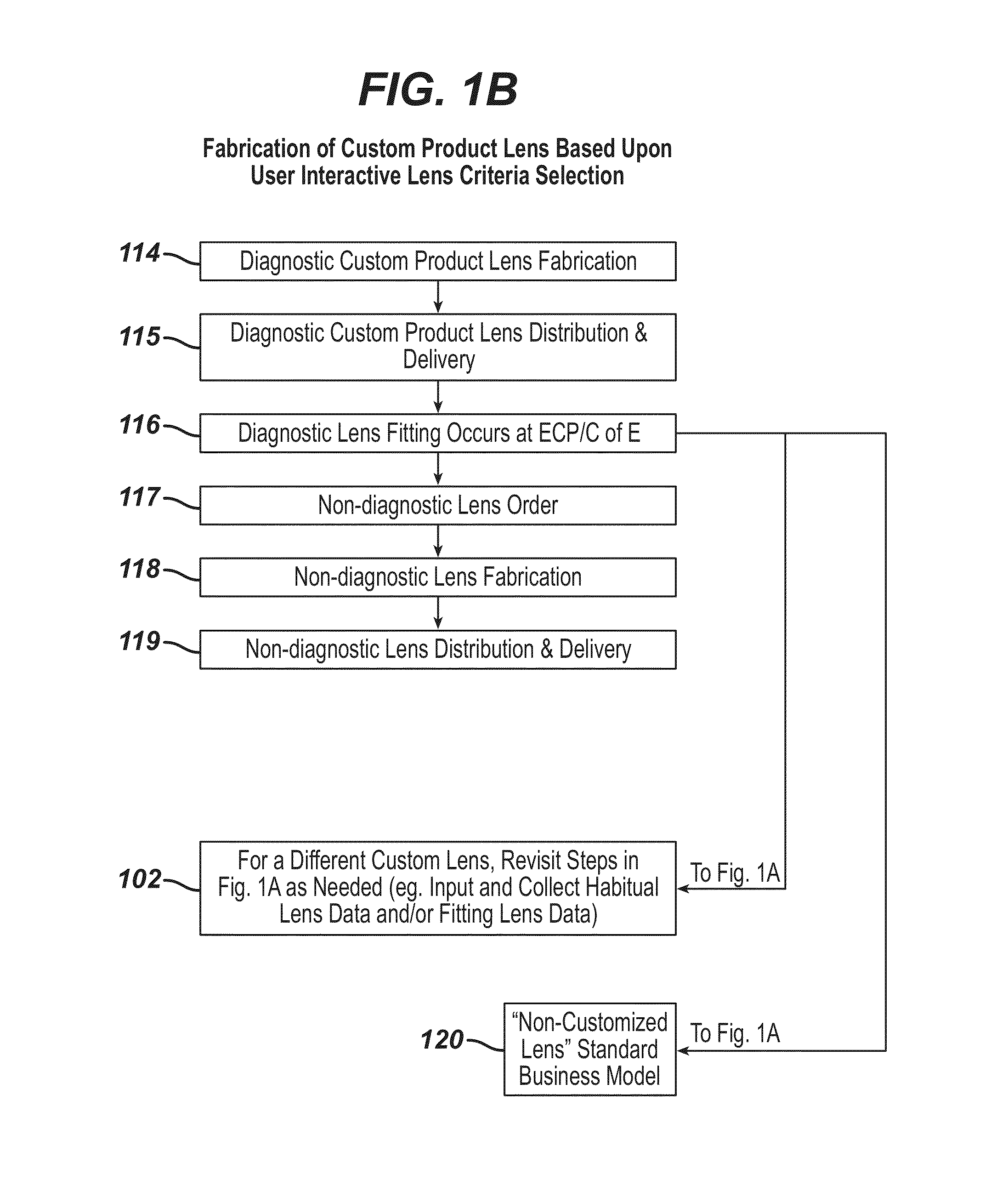
[0084]FIG. 1A is a block diagram showing a system and method for providing a custom lens to a patient according to an embodiment of the invention, wherein user / patient interactive lens criteria selection is employed. Although the implementation of the method steps may begin at an eye care practitioner's office or at some sort of vision center, the invention should not be limited to these locations. Referring to FIG. 1A, a patient is provided an overview of available products and services 101. User interactive tools that demonstrate various potential use experiences can be employed. User interactive tools can be employed to collect and store data regarding the patient 102. This data can be used to generate information regarding products and services specific to the patient 103. Such data can include the patient's age, medical conditions that the patient suffers, e.g., diabetes, hypertension, etc., eye or vision related medical conditions, e.g., glaucoma, dry-eye syndrome, etc., visio...


PUM


Abstract

A method, system and apparatus for providing vision correction to a patient is disclosed. The method, system and apparatus involve a) obtaining at least one bare eye data measurement, habitual lens data measurement and / or fitting lens data measurement of the patient; b) providing the at least one bare eye data measurement, the habitual lens data measurement and / or the fitting lens data measurement to a free form custom lens manufacturing system; c) producing a customized lens using the free form custom lens manufacturing system; and d) providing the custom lens to the patient.

Description

CROSS-REFERENCE TO RELATED APPLICATIONS[0001]This application is a Non-Provisional of U.S. Ser. No. 61 / 664,963 filed Jun. 27, 2012. The complete disclosure of the aforementioned related U.S. patent application(s) is hereby incorporated herein by reference for all purposes.BACKGROUND OF THE INVENTION[0002]1. Field of the Invention[0003]The present invention relates to the field of vision correction and, more particularly, to methods and systems for providing customized vision correction, and business methods associated with providing such correction. The methods and systems employ a free form custom manufacturing process to form a custom contact lens.[0004]2. Description of Related Art[0005]A large portion of the population is ametropic; i.e., their vision is less than optimum due at least in part to refractive abnormalities of the eye. For over 100 years, practitioners ranging from lens fitters to surgeons have engaged in the business of providing vision correction to the ametropic ...

Claims


Application Information

Patent Timeline
IPC IPC(8): G02C7/02A61B3/00A61B3/02A61B3/10A61B3/107
CPCG02C7/027A61B3/10A61B3/107A61B3/02A61B3/0025A61B3/00G02C7/04A61F2/16A61F9/00G06Q50/04G02C7/02
Inventor WILDSMITH, CHRISTOPHER
Owner JOHNSON & JOHNSON VISION CARE INC
Learn More