Common-core power factor correction resonant converter

Active Publication Date: 2014-01-02
MACROBLOCK INC
View PDF1 Cites 2 Cited by
  • Summary
  • Abstract
  • Description
  • Claims
  • Application Information

AI Technical Summary

Benefits of technology

This patent describes a power converter that uses a common-core design to improve power factor and reduce losses. It achieves this by switching between different resonant circuits to capture input line power and convert it to output power. This results in a more efficient and compact circuit that can use lower voltage components and achieve better power factor, reducing electromagnetic interference. Overall, this design offers an affordable and efficient solution for power conversion.

Problems solved by technology

Thus the circuit is not suitable for low-voltage output.
However, this circuit can not provide high power factor function.
However, the power factor correction resonant converter adopts two separate inductors (elements 110 and 120, respectively), and is implemented by using five diodes, such that the cost and the volume of the circuit elements increase, and the component conduction loss also increase.

Method used


Image

  • Common-core power factor correction resonant converter
  • Common-core power factor correction resonant converter
  • Common-core power factor correction resonant converter

Examples


Embodiment Construction

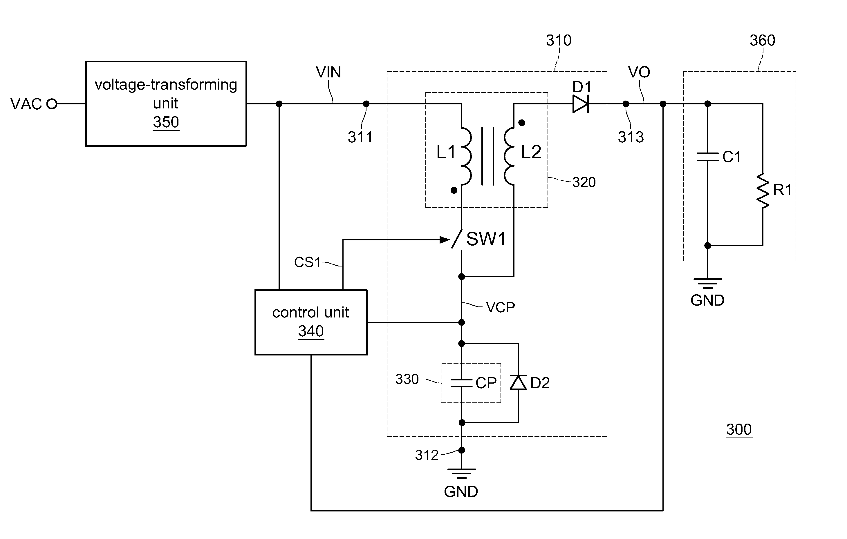
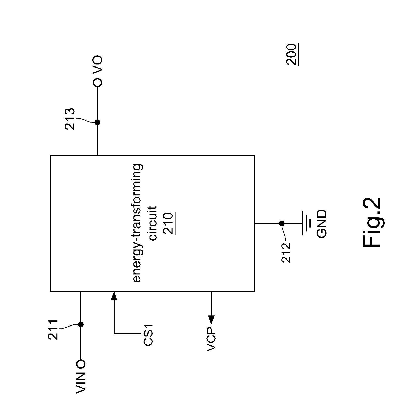
[0018]FIG. 2 is a circuitry diagram of a common-core power factor correction resonant converter of the present disclosure. FIG. 3 is an embodiment of the detailed circuit diagram of the common-core power factor correction resonant converter in FIG. 2.

[0019]Referring to FIG. 2, the common-core power factor correction resonant converter 200 may be referred as a coupling-inductor power factor correction resonant converter. The common-core power factor correction resonant converter 200 includes an energy-transforming circuit 210.

[0020]The energy-transforming circuit 210 includes a first terminal 211, a second terminal 212, and a third terminal 213. The first terminal 211 of the energy-transforming circuit 210 receives an input line voltage VIN, the second terminal 212 of the energy-transforming circuit 210 is coupled to a ground GND, and the third terminal 213 of the energy-transforming circuit 210 generates an output power VO.

[0021]Furthermore, the energy-transforming circuit 210 inclu...


PUM


Abstract

A common-core power factor correction resonant converter includes an energy-transforming circuit. The energy-transforming circuit receives an input line voltage and generates an output power. The energy-transforming circuit includes a coupling inductor and a charge-storage capacitor. The coupling inductor and the charge-storage capacitor are charged by the input line voltage in response to a control signal, so as to generate a charge-storage capacitor voltage. When the charge-storage capacitor voltage is charged to a preset voltage level, the coupling inductor and the charge-storage capacitor are discharged according to the control signal. Then, the energy in the coupling inductor and the charge-storage capacitor is transformed to the output load and provide the output voltage or current regulation.

Description

CROSS-REFERENCE TO RELATED APPLICATIONS[0001]This non-provisional application claims priority under 35 U.S.C. §119(a) on Patent Application No(s). 101123093 filed in Taiwan, R.O.C. on Jun. 27, 2012, the entire contents of which are hereby incorporated by reference.BACKGROUND[0002]1. Technical Field[0003]The disclosure relates to a power factor correction convertor, and more particularly to a common-core power factor correction resonant converter.[0004]2. Related Art[0005]In general, the circuit structure of a power factor correction converter usually uses the inductors as energy storage devices. The inductor further combines with the boost topology control architecture to achieve power factor correction effect such that the energy may be transferred to the loads. The output voltage of this type of converter must be higher than the voltage of the line power source. Thus the circuit is not suitable for low-voltage output. Therefore, it is necessary to change the circuit to the step-do...

Claims


Application Information

Patent Timeline
IPC IPC(8): G05F1/70
CPCG05F1/70H02M3/137H02M3/335Y02B70/10Y02P80/10H02M1/42H02M3/07
Inventor CHANG, LON-KOUHUANG, YI-WENHUANG, HAN-HSIANG
Owner MACROBLOCK INC
Why Eureka
Try Eureka