Electronic ballast circuit with function of correcting power factor and load current amplitude factor

An electronic ballast, load current technology, applied in electric light sources, electrical components, lighting devices, etc., can solve problems such as increasing circuit complexity, and achieve the effect of good power factor

Inactive Publication Date: 2003-06-04
DELTA ELECTRONICS INC
View PDF0 Cites 6 Cited by
  • Summary
  • Abstract
  • Description
  • Claims
  • Application Information

AI Technical Summary

Problems solved by technology

In order to achieve better power performance, the existing electronic ballast circuit still needs to add many components to improve performance. However, this will increase the circuit complexity, energy loss on the components, and the cost of the components

Method used


Image

  • Electronic ballast circuit with function of correcting power factor and load current amplitude factor
  • Electronic ballast circuit with function of correcting power factor and load current amplitude factor
  • Electronic ballast circuit with function of correcting power factor and load current amplitude factor

Examples


Embodiment Construction

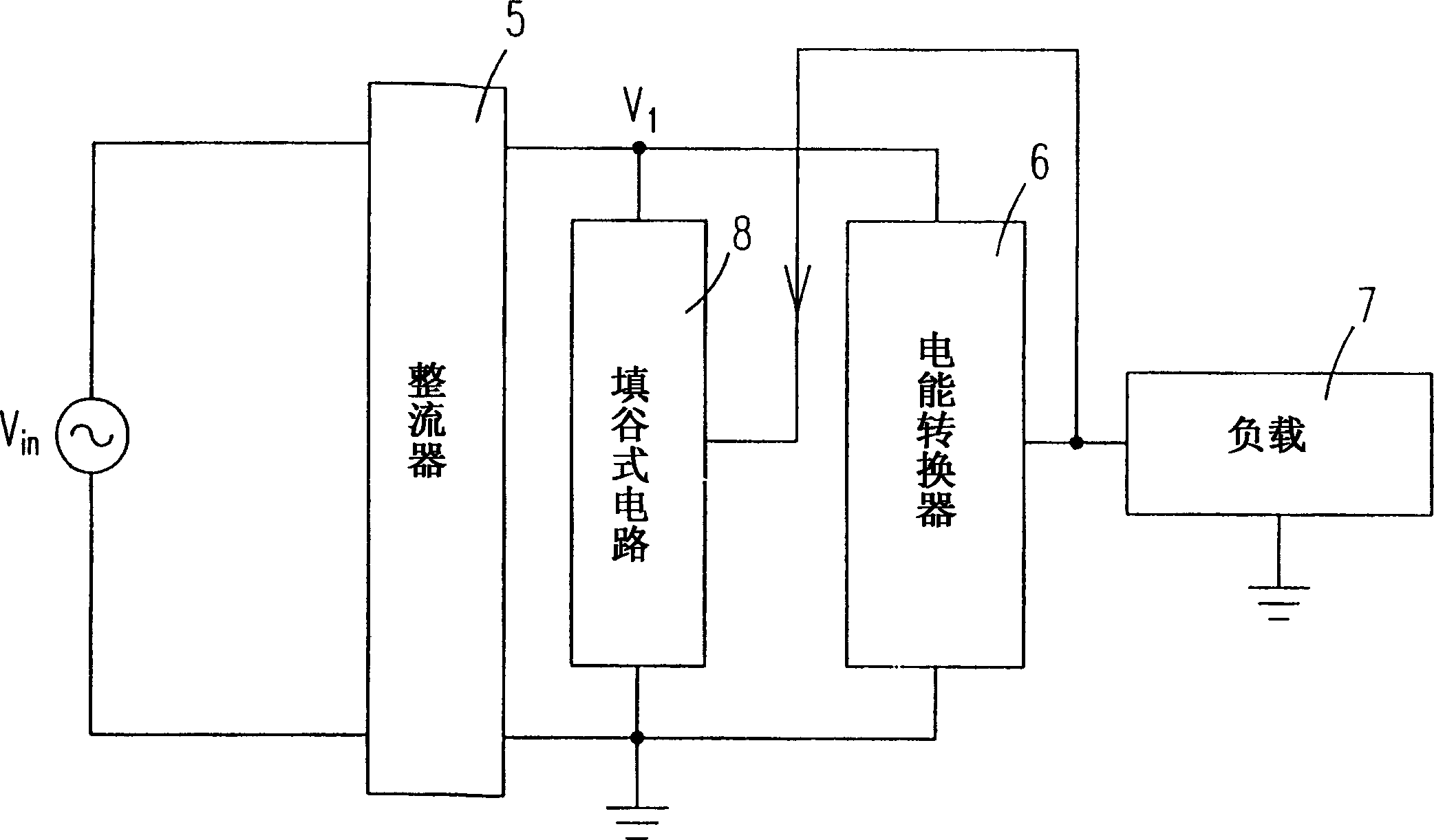
[0025] see figure 2 , is the circuit block diagram of the electronic ballast circuit with power factor and load current crest factor correction function according to the first preferred embodiment of the present invention. Such as figure 2 As shown, an electronic ballast circuit with power factor and load current crest factor correction function is electrically connected to an input power supply, which provides an input voltage V in , the electronic ballast circuit includes: a rectifier 5, a power converter 6 and a valley fill circuit (valley fill circuit) 8. The rectifier 5, which is electrically connected to the input voltage V in , the input voltage V in rectified to provide a first voltage V 1 . The power converter 6 is electrically connected to the rectifier 5, and the first voltage V 1 Do high-frequency switching output to provide electric energy for a load 7 . And, the valley-filling circuit 8 is electrically connected to an output end of the power converter 6 an...


PUM


Abstract

The electronic ballast circuit is connected electrically to an input power supply to provide input voltage. The electronic ballast circuit includes one rectifier connected to the input voltage for rectifying and providing one first voltage; one electric energy converter to switch and output the HF component in the first voltage and to provide electric energy to the load; and one valley fill circuit connected to the output of the electric energy converter and the output of the rectifier. When the first voltage is higher than some set value, the electric energy converter is switched to charge the valley fill circuit; and when the first voltage is lower than the set value, the valley fill circuit is used to make up the first voltage, with the set value being regulated in designing the valley fill circuit.

Description

technical field [0001] The invention relates to an electronic ballast circuit with the correction function of power factor and load current amplitude factor, especially an electronic ballast circuit with the correction function of power factor and current amplitude factor using a valley-filling circuit. Background technique [0002] The existing electronic ballast circuit is to drive a gas discharge lamp load 4, as shown in Figure 1(a) and (b), the electronic ballast circuit mainly includes an AC input power supply 1, a rectifier 2 and a High frequency power converter circuit 3. The high frequency power converter circuit 3 includes a high frequency switching circuit 31 and a resonant circuit 32 , and the gas discharge lamp load 4 is electrically connected to the electronic ballast circuit through the resonant circuit 32 . [0003] The main purpose of designing an electronic ballast circuit is to achieve optimal power performance, that is, to obtain optimal power factor (pow...

Claims


Application Information

Patent Timeline
Patent Type & Authority Applications(China)
IPC IPC(8): H05B41/14H05B41/28
Inventor 刘晨阳章进法许富渊
Owner DELTA ELECTRONICS INC
Why Eureka
Try Eureka