
Tube-shaped part and an associated method of manufacture

a technology of tube-shaped parts and associated methods, which is applied in the direction of coating, chemistry apparatus and processes, lamination ancillary operations, etc., can solve the problems of difficult to apply anti-splinter film and desired decoration to the interior surface and achieve the effect of efficient fabrication of the tube-shaped par

Active Publication Date: 2014-01-02
NOKIA TECHNOLOGLES OY
View PDF6 Cites 12 Cited by
  • Summary
  • Abstract
  • Description
  • Claims
  • Application Information

AI Technical Summary

Benefits of technology

The present invention provides a tube-shaped assembly, a tube-shaped part, and a method of manufacturing them. The tube-shaped part is a closed and seamless tube that provides protection for internal electronic components. The method of manufacturing allows for efficient and repeatable fabrication of the tube-shaped part. The technical effects include improved protection for internal components while maintaining aesthetically pleasing appearance.

Problems solved by technology

While a closed and seamless tube-shaped part may provide improved protection for the internal electronic components, a closed and seamless tube-shaped part may create manufacturing challenges.
As a result of the closed and seamless construction of a tube-shaped part, however, it may prove difficult to coat the tube-shaped part with an anti-splinter film and to provide the desired decoration, such as tinting, to the tube-shaped part.
However, the closed and seamless construction of a tube-shaped part may limit the accessibility to the interior surface of the tube-shaped part and may make it difficult to apply the anti-splinter film and the decoration, such as the tinting, to the interior surface of the tube-shaped part.

Method used


Image

  • Tube-shaped part and an associated method of manufacture
  • Tube-shaped part and an associated method of manufacture
  • Tube-shaped part and an associated method of manufacture

Examples


Embodiment Construction

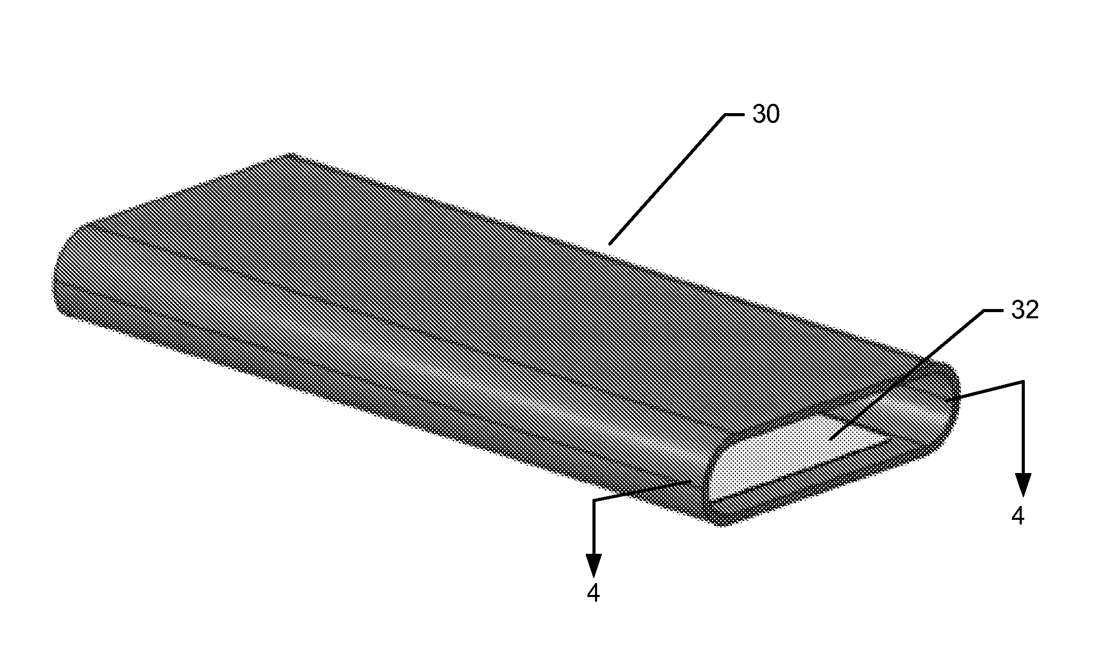
[0018]Some embodiments of the present invention will now be described more fully hereinafter with reference to the accompanying drawings, in which some, but not all, embodiments of the invention are shown. Indeed, various embodiments of the invention may be embodied in many different forms and should not be construed as limited to the embodiments set forth herein; rather, these embodiments are provided so that this disclosure will satisfy applicable legal requirements. Like reference numerals refer to like elements throughout. As used herein, the terms “data,”“content,”“information,” and similar terms may be used interchangeably to refer to data capable of being transmitted, received and / or stored in accordance with embodiments of the present invention. Thus, use of any such terms should not be taken to limit the spirit and scope of embodiments of the present invention.

[0019]An apparatus, such as a tube-shaped part or a tube-shaped assembly, and an associated method for manufacturin...


PUM

PropertyMeasurementUnit
Forceaaaaaaaaaa
Optical propertiesaaaaaaaaaa

Abstract

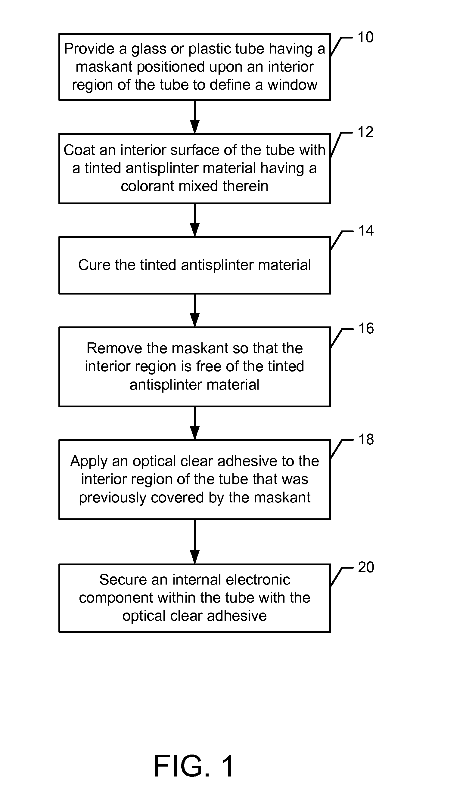
A tube-shaped assembly, a tube-shaped part and an associated method of manufacturing the same are provided. In regards to a method, a glass or plastic tube is provided that has a maskant positioned upon an interior region of the tube to define a window. The method also includes coating an interior surface of the tube with a tinted anti-splinter material having a dye or pigment mixed therein. The method also includes curing the tinted anti-splinter material and removing the maskant such that the interior region is free of the tinted anti-splinter material. A tube-shaped part is also provided that includes a glass or plastic tube and a maskant positioned upon an interior region of the tube to define a window. The tube-shaped part also includes a tinted anti-splinter material having a dye or pigment mixed therein.

Description

TECHNOLOGICAL FIELD[0001]An example embodiment of the present disclosure relates generally to tube-shaped parts and associated methods for manufacture and, more particularly, to tube-shaped parts having a decorative anti-splinter film and associated methods for manufacture.BACKGROUND[0002]Tube-shaped parts made of glass or plastic are utilized for various purposes. For example, electronic devices, such as various types of mobile terminals, e.g., cellular telephones, smartphones, music players, gaming devices or the like, may include a tube-shaped part that serves as the housing and that structurally protects and carries the internal electronic components that are positioned within the tube-shaped part.[0003]In order to provide enhanced protection for the internal electronic components, the tube-shaped part may be closed and seamless. In this regard, the tube-shaped part may have opposed open ends, but may otherwise be closed and seamless so as to not define any openings in the sidew...

Claims


Application Information

Patent Timeline
IPC IPC(8): F16L55/00B32B37/12B32B37/02B05D7/22B05D5/10
CPCB05D7/22B05D1/32
Inventor LASAROV, HARRI AUKUSTIVEHKAPERA, VILLE HENRIKKI
Owner NOKIA TECHNOLOGLES OY
Learn More