
Security System and Method using Wireless Adapters and PoE Cameras

a technology of wireless adapters and security cameras, which is applied in the field of security systems and methods using wireless adapters and poe cameras, can solve the problems of increasing r&d expenses, increasing installation costs for each camera, and increasing the cost of deployment of the device, so as to increase the installation cost of each camera, increase manufacturing costs, and increase the effect of cos

Inactive Publication Date: 2013-12-26
JOHNSON CONTROLS TYCO IP HLDG LLP
View PDF5 Cites 33 Cited by
  • Summary
  • Abstract
  • Description
  • Claims
  • Application Information

AI Technical Summary

Benefits of technology

The patent describes a solution to the problem of needing separate power sources for cameras and other security devices on a network. The solution is a wireless adapter that supports multiple cameras and other devices with a single power source, reducing installation and manufacturing costs. The patent also mentions that the same standard camera can be used for both standard wired connections and wireless connections with the wireless adapter.

Problems solved by technology

Providing integrated wireless capabilities into the cameras is problematic because it creates added costs.
Therefore, this means more R&D expenses along with increased manufacturing and inventory costs.
Furthermore, the integrated camera will also require future support costs due to potential functional problems with the internal adapter.
The problem is that using conventional wireless adapters, a separate power source for the camera is still required.
This increases installation costs for each camera because each device needs to be connected upon installation.
Connecting each device to a power source and to the adapter impacts the cost to deploy the device.
Also, this increases manufacturing costs since each camera now requires a power jack and a data jack.
Adding these jacks increases the overall manufacturing cost of the device.

Method used


Image

  • Security System and Method using Wireless Adapters and PoE Cameras
  • Security System and Method using Wireless Adapters and PoE Cameras
  • Security System and Method using Wireless Adapters and PoE Cameras

Examples


Embodiment Construction

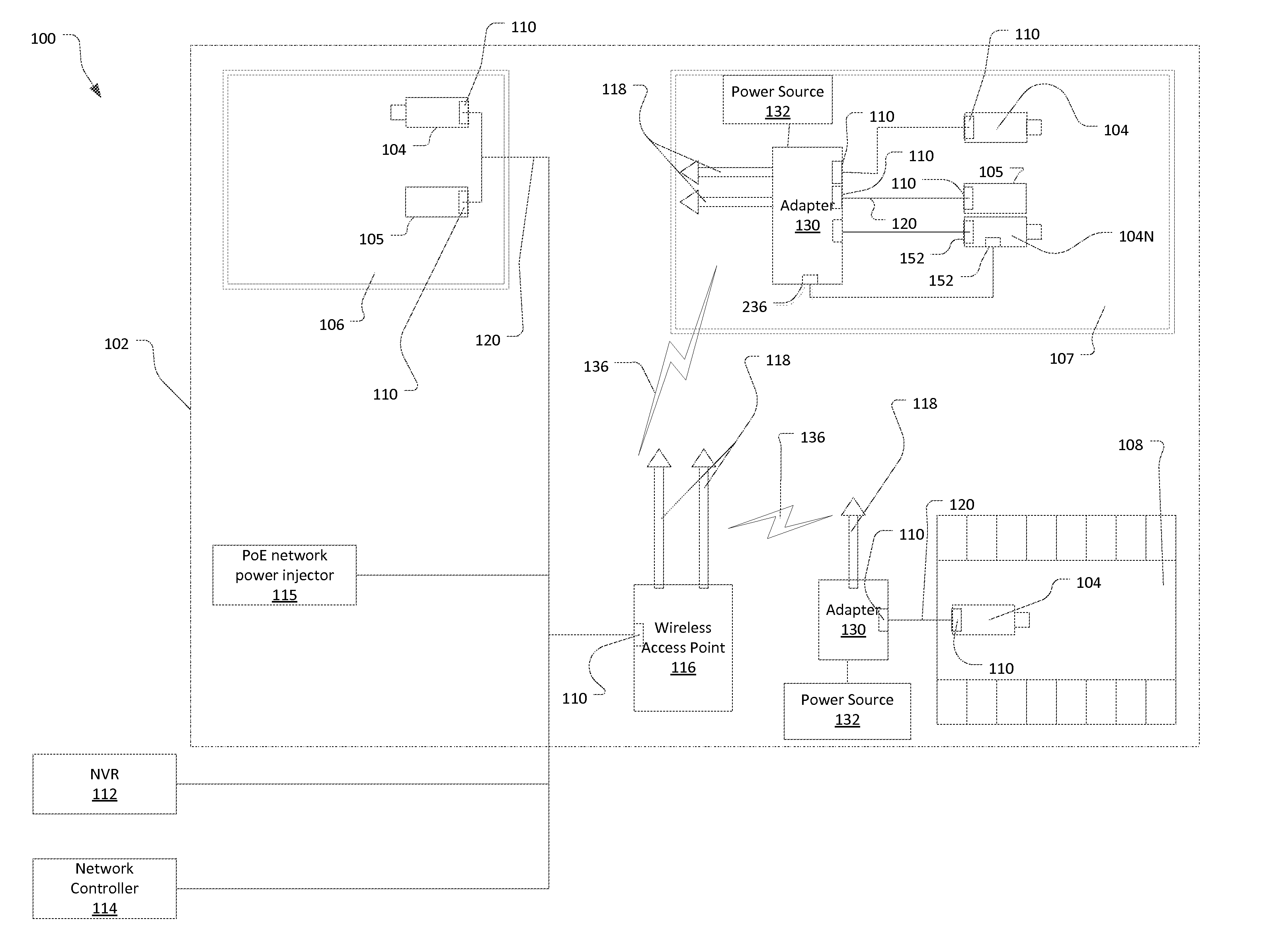
[0023]FIG. 1 shows a security network system 100 and wireless adapter 130 that have been constructed according to the principles of the present invention.

[0024]In one example, the security network system 100 is deployed at an installation 102 such as an office complex, a single building or a larger institution. The installation 102 includes remote wired security devices 104, 105 distributed throughout the installation 102. For example, two security devices 104, 105 are located inside a building 106. Another security device 104 is positioned outside in a parking lot area 108. Three security devices 104, 105 are located inside another building 107.

[0025]Some of the wired security devices are security cameras and preferably IP security cameras 104. Each of these IP security cameras 104 is positioned to observe and record images from an area under observation. These IP security cameras 104 preferably each include a combined data / power physical port 110.

[0026]In the security network syst...


PUM


Abstract

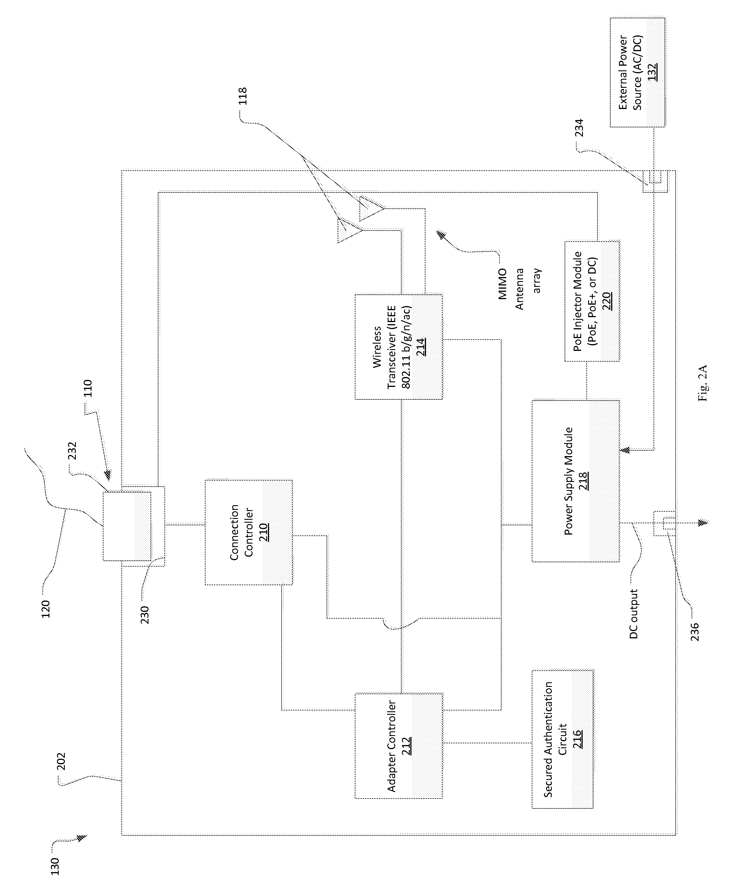
A wireless adapter and method for providing a wireless connection to at least one wired security device includes at least one combined data / power physical port to which the wired security device connects. A power supply module receives power from an external power source and a power injector provides power to the combined data / power physical port to thereby power the wired security device. In this way, the wireless adapter supplies both power and data connection at the same physical port / jack of the wired security devices, such as IP security cameras, via an interface cable from the wireless adapter. This configuration has advantages in lowering the manufacturing costs of the cameras and reducing installation costs. Furthermore, the same standard camera can be used for both standard wired connections and wireless connections.

Description

BACKGROUND OF THE INVENTION[0001]Security network systems are often used for monitoring activities in and around residential and commercial buildings. Security networks typically include keypads or other access control devices, system controllers, a variety of intrusion sensors, security cameras, and network video recorders (NVRs) that connect to each other through a common wired network.[0002]One type of security camera that is often used within security network systems is an internet protocol (IP) security camera. The IP security camera differs from closed circuit television cameras in that it can send and receive data via a network and utilizes the internet protocol address schema.[0003]IP security cameras can be used to monitor buildings and rooms within buildings and can also be used to monitor public areas such as parks or public spaces in and around buildings. In some cases they are used to catch illegal activity. In other cases, they are used to monitor shopping patterns in ...

Claims


Application Information

Patent Timeline
Patent Type & Authority Applications(United States)
IPC IPC(8): H04B1/38H04N7/18
CPCH04L12/10
Inventor SIU, PATRICK
Owner JOHNSON CONTROLS TYCO IP HLDG LLP
Learn More