
Control System for Downhill Skis

a control system and ski technology, applied in the direction of skis, vehicle components, braking element arrangements, etc., can solve the problems of increasing the likelihood of two skis being engaged, difficulty in steering the skis, and difficulty at times for skiers to maintain speed at a safe and comfortable level and/or to respond, so as to achieve a high level of control and keep speed at a comfortable level.

Inactive Publication Date: 2013-12-26
MANN SAMUEL J
View PDF12 Cites 9 Cited by
  • Summary
  • Abstract
  • Description
  • Claims
  • Application Information

AI Technical Summary

Benefits of technology

The present invention is a control system for skiers that allows them to have high control over their speed while skiing downhill. The system includes braking elements that can be projected from the ski to control its movement on the snow surface. The braking elements can be adjusted to different positions to provide varying levels of resistance for the skier to control their speed. This allows the skier to maintain a comfortable speed level as they encounter different terrains and conditions, and to adjust their speed in anticipation of challenges. The system also enables the skier to maintain optimal ski and body position for better control and more enjoyable skiing experience.

Problems solved by technology

Regardless of the level of skill of the skier, however, the condition of a particular area of terrain, unsatisfactory weather conditions, reduced visibility toward the end of the day and / or fatigue can make it difficult at times for a skier to maintain speed at a safe and comfortable level and / or to respond to an emergency condition or obstacle.
Moreover, when the trailing end devices are actuated, they can make steering of the skis difficult by tending to hold the ski tails on a pre-existing path instead of allowing them to freely move laterally to enable the skier to change the direction of the skis.
This increases the likelihood of the two skis becoming engaged during skiing to interfere with the skier's control and also provides exposed sharp edges that could result in injury in a fall.

Method used


Image

  • Control System for Downhill Skis
  • Control System for Downhill Skis
  • Control System for Downhill Skis

Examples


Embodiment Construction

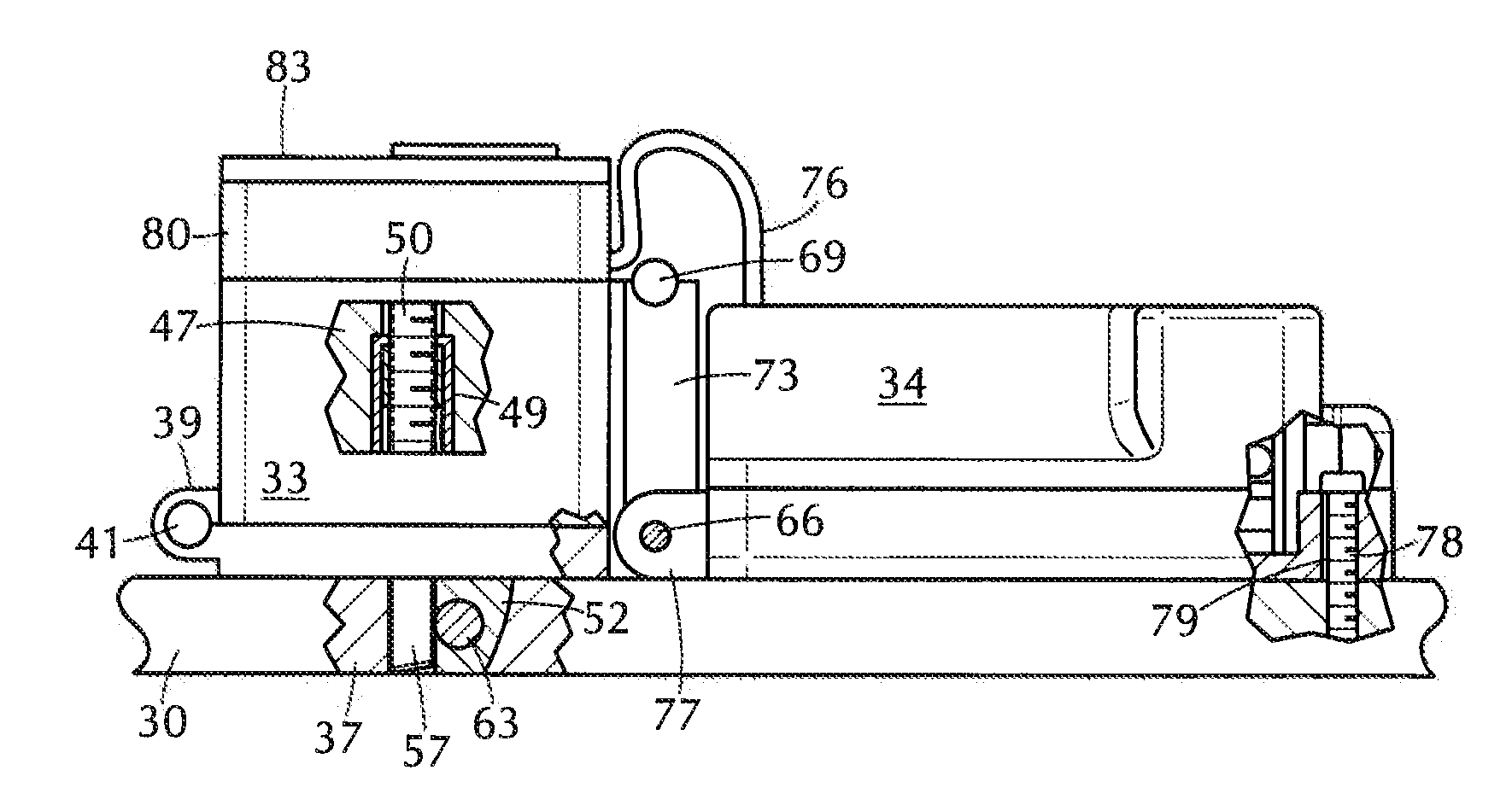
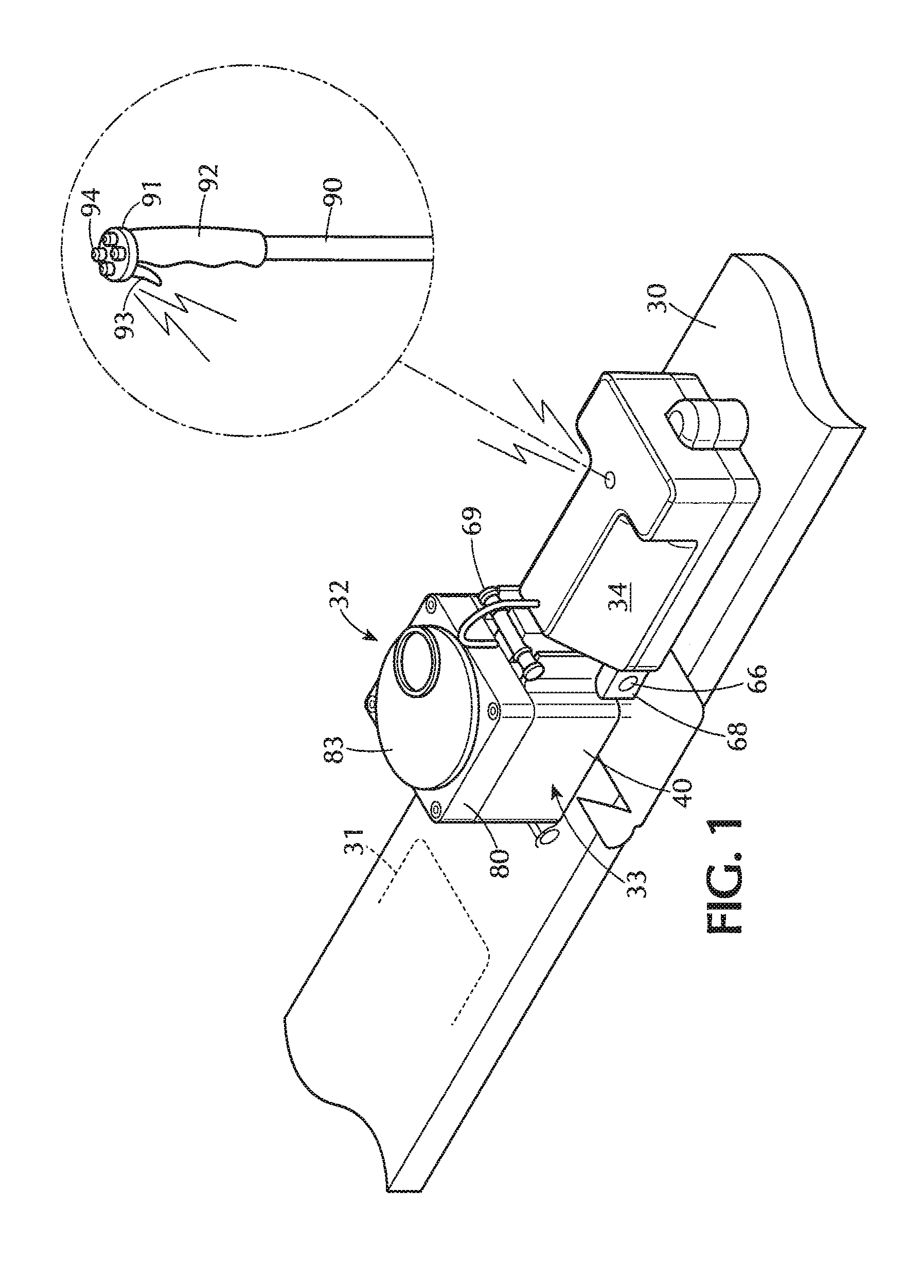
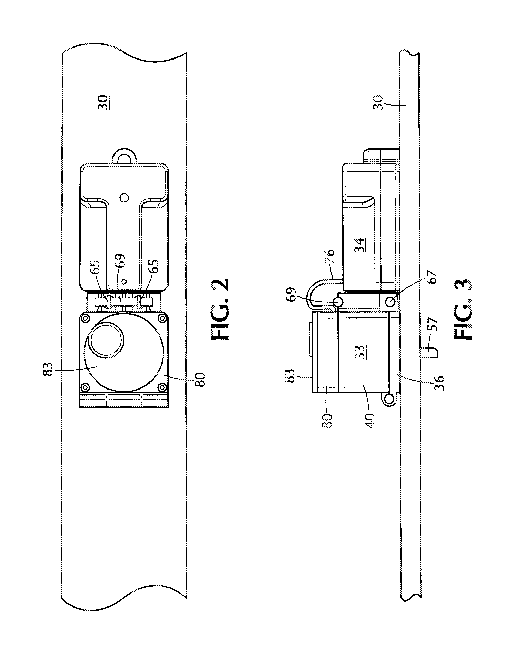
[0039]Referring to the drawings, the reference numeral 30 designates a typical ski on which is mounted a boot binding, indicated schematically at 31. Closely adjacent to and behind the boot binding 31 is the braking system of the invention, designated generally by the reference numeral 32. The braking system 32 comprises a motor unit 33 and a battery box 34, which also houses electronic controls for the motor unit 33. The motor unit 33 comprises a base member 35 (see FIGS. 7-9), which includes a mounting flange 36 and a downwardly projecting cylindrical portion 37. The cylindrical portion 37 has a diameter which is somewhat less than the width of the ski, and is received in a cylindrical through opening 38 provided in the ski (FIG. 6). For example, in a practical embodiment of the invention, the cylindrical projection may have a diameter of about 1.875 inches, for installation on a ski, the width of which, in the region of the boot binding 31, may be approximately 3.25 inches. The f...


PUM


Abstract

A control system for downhill skis enables effective, continuous control of ski-to-surface resistance, to accommodate changing steepness and other conditions during a downhill ski run. Controllably positionable brake elements are mounted on the skis, centrally between the side edges thereof. Positioning motors are mounted on each ski and are operable to controllably project or retract the brake elements relative to the ski bottoms, continuously or in finite increments, allowing the skier to maintain a safe and comfortable skiing experience over almost any ski slope under a wide variety of ski conditions. The braking elements, preferably blade-like and oriented at right angles to the ski axis, are positioned close to the skier's feet, allowing the skis to be easily controlled in turns and other maneuvers. A spring-loaded, hinged mounting arrangement allows the mechanisms to momentarily pivot to retracted positions whenever the braking elements engage a rock or other immovable object.

Description

FIELD OF THE INVENTION[0001]This invention relates to speed control arrangements for downhill skis, to enable downhill skiers to better control their speed of descent. In principle, and invention is also applicable to other snow recreational devices that slide over a snow surface, such as snow boards. toboggans and the like.BACKGROUND OF THE INVENTION[0002]In downhill skiing, speed of descent can be controlled in a variety of ways, depending upon factors such as steepness of the slope, snow conditions, irregularities in the terrain, skill and strength of the skier, etc. A skilled skier can check speed by executing a series of turns in relatively rapid succession while maintaining a generally downward trajectory. A less skilled person may tend to ski laterally back and forth across the slope, minimizing the vertical component of the path and executing less frequent turns. Regardless of the level of skill of the skier, however, the condition of a particular area of terrain, unsatisfac...

Claims


Application Information

Patent Timeline
IPC IPC(8): A63C7/10
CPCA63C7/1086A63C2203/22
Inventor MANN, SAMUEL J.
Owner MANN SAMUEL J
Learn More