
Unbonded flexible pipe

a flexible pipe and unbonded technology, applied in the direction of flexible pipes, hose connections, mechanical equipment, etc., can solve the problems of reducing the durability of pipes, and achieve the effect of reducing the potential corrosion of metallic elements, substantially reducing the life of unbonded flexible pipes, and avoiding potential corrosion

Inactive Publication Date: 2013-12-26
NAT OILWELL VARCO DENMARK
View PDF8 Cites 12 Cited by
  • Summary
  • Abstract
  • Description
  • Claims
  • Application Information

AI Technical Summary

Benefits of technology

The invention is a flexible pipe that has a pathway to keep it clean and prevent corrosion. This increases the life of the pipe and reduces the need for maintenance. This pipe is not much more expensive or complicated to make than other flexible pipes. Drying the pipe and keeping it dry also increases its lifespan and reduces the potential for corrosion.

Problems solved by technology

Accordingly it has been found that even though the penetrated gas is allowed to escape to avoid overpressure, the penetrated gas causes an undesired corrosion of armouring elements provided in the annulus and in general such penetration of gasses has shown to reduce the durability of the pipe.

Method used


Image

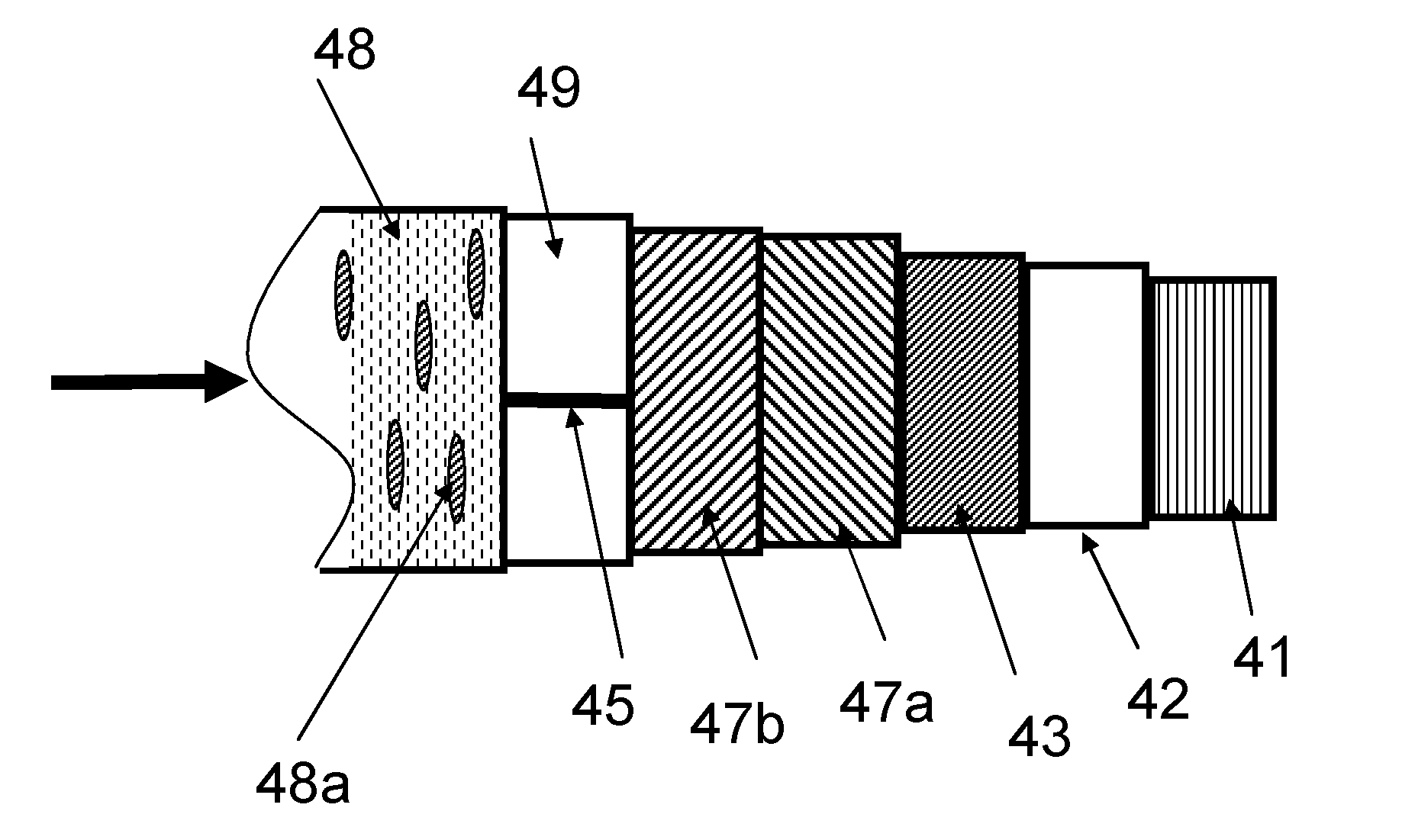
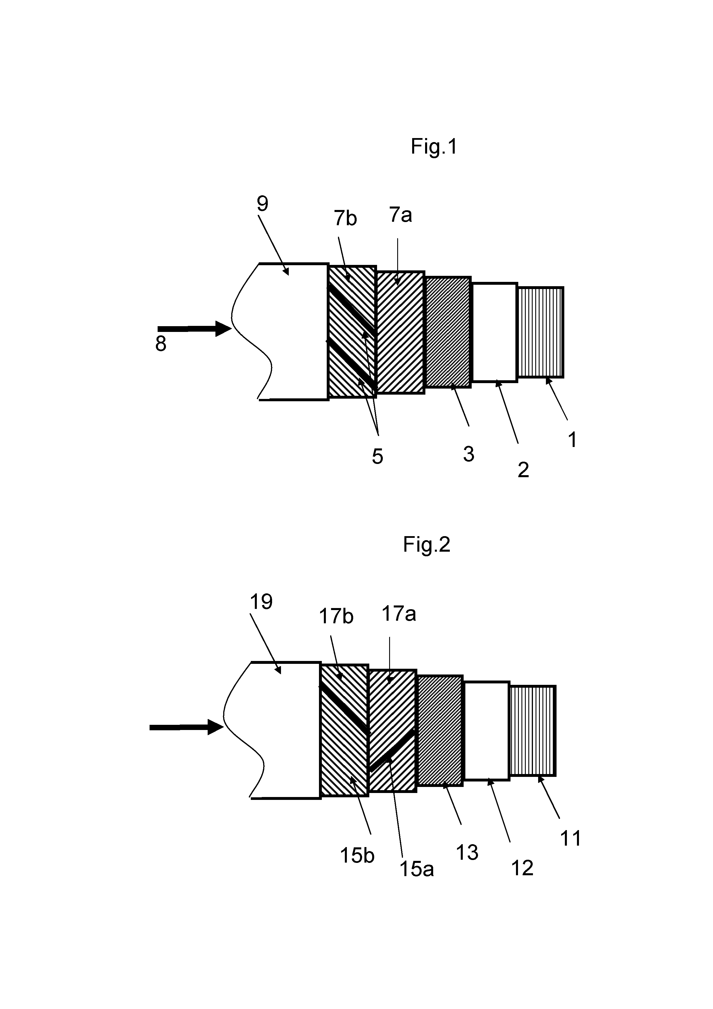
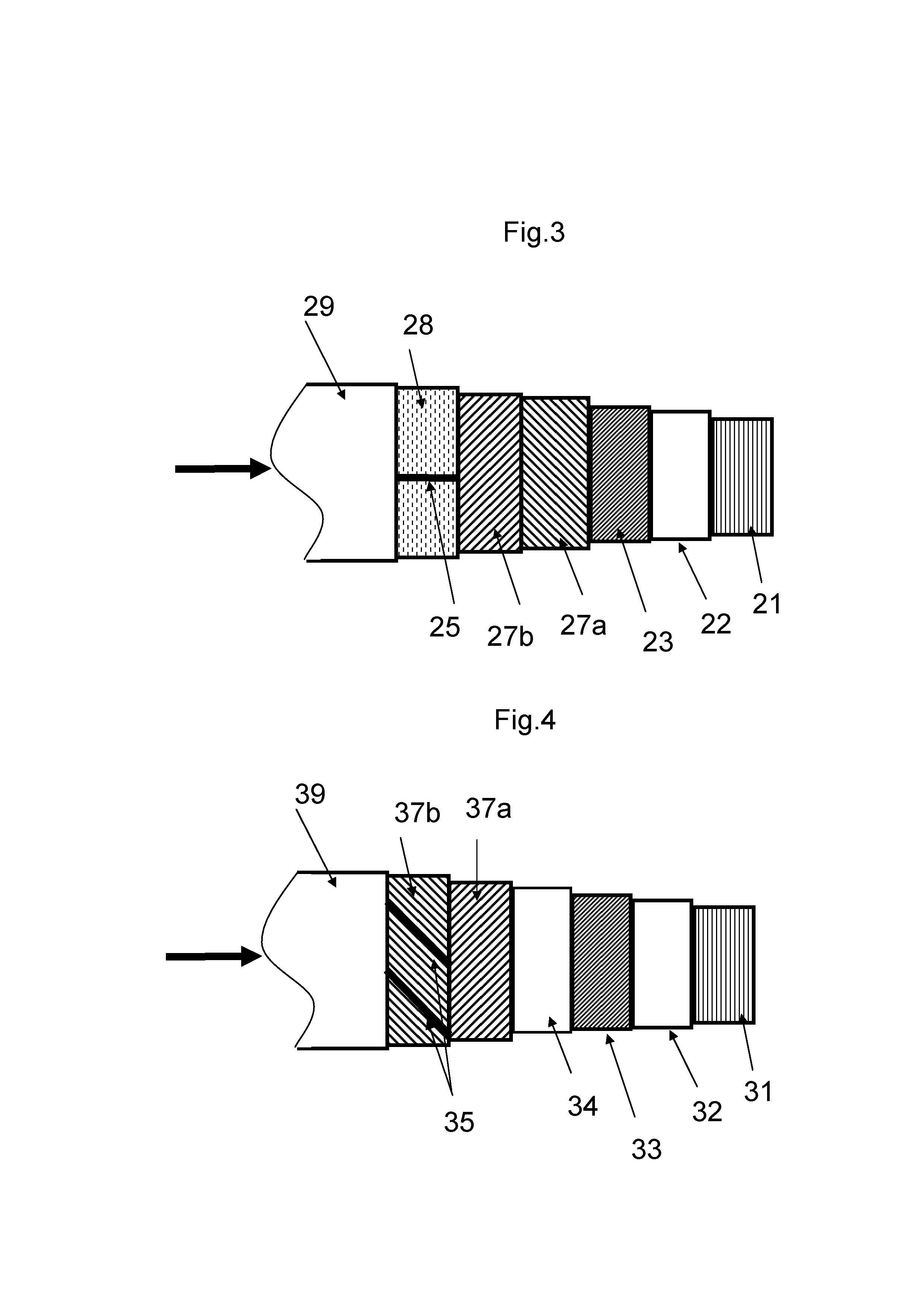
  • Unbonded flexible pipe
  • Unbonded flexible pipe
  • Unbonded flexible pipe

Examples


example 1

[0194]A 900 m long riser pipe is produced. The riser pipe has the following layers from inside and out:[0195]A carcass of duplex steel[0196]An inner sealing sheath of Polyamide (PA), with a thickness of 8 mm.[0197]2 cross wound tensile armour layers of duplex steel[0198]An outermost sealing sheath of polyethylene (PE), with a thickness of 8.5 mm.

[0199]One of the tensile armouring elements of the outermost tensile armouring layer is replaced with a maintaining pipe.

[0200]The pipe is terminated with a first (uppermost) end-fitting and a second (lower most) end-fitting.

[0201]In the second end-fitting the maintaining pipe is connected to the annulus to provide a pathway from the upper end of the riser via the fluidic connection in the second end-fitting and to the upper end of the riser.

[0202]The riser is installed at a production site for transporting crude oil from a well to a sea-surface installation (e.g. a platform).

[0203]The sum of CO2, CH4, H2S and H2O entering the annulus from t...

example 2

[0223]The installed pipe of example 1 is subjected to a constant flushing of the annulus via the pathway provided by the maintaining pipe and the annulus with 20.85 litre dry air per hour.

[0224]A similar pipe, but without the maintaining pipe and without flushing of annulus, is installed and set to a similar operation as the pipe of example 1.

[0225]Calculation shows that the fatigue damage after 20 years of the riser of example 1 with a dry annulus is much lower that the fatigue damage after 20 years of the riser without a maintaining pipe and therefore with a wet annulus.


PUM


Abstract

The invention relates to an unbonded flexible pipe for sub sea transportation of fluids. The pipe has a length and comprises a tubular inner sealing sheath defining a bore and an axis of the pipe. In a pipe length section it comprises a second sealing sheath surrounding the inner sealing sheath and forming an annulus between the inner sealing sheath and the second sealing sheath. The annulus provides a primary maintaining passage along the length of the pipe length section with a first and a second end. The pipe comprises at least one secondary maintaining passage along the length of the pipe with a first and a second end. The secondary maintaining passage is arranged with an axial distance which is larger than the axial distance of the inner sealing sheath. The first end of one of the primary and the secondary maintaining passages is arranged as an input end for a maintaining fluid and the first end of the other of the primary and the secondary maintaining passages is arranged as an outflow end for the maintaining fluid, and the primary and the secondary maintaining passages are in fluidic connection with each other at their second ends to provide a pathway for the maintaining fluid.The pathway for a maintaining fluid makes it possible in a simple and effective manner to keep the corrosion of elements—such as armouring elements in the annulus—relatively low, and accordingly the duration of the unbonded flexible pipe can thereby be increased.

Description

TECHNICAL FIELD[0001]The invention relates to a flexible pipe for transportation of fluids in offshore applications and in particular for transportation of gas containing fluids such as hydrocarbons.BACKGROUND ART[0002]Flexible pipes of the present type for offshore transportation of fluids are well known in the art and are for example described in “Recommended Practice for Flexible Pipe”, API 17 B, second Edition, 1998, which provides a standard for such pipes. Such pipes usually comprise an inner liner also often called an inner sealing sheath or an inner sheath, which forms a barrier against the outflow of the fluid which is conveyed through the pipe, and one or more armouring layers on the outer side of the inner liner (outer armouring layer(s)). An outer sealing sheath may be provided with the object of forming a barrier against the ingress of fluids from the pipe surroundings to the armour layers.[0003]Typical unbonded flexible pipes are e.g. disclosed in WO0161232A1, U.S. Pat...

Claims


Application Information

Patent Timeline
IPC IPC(8): F16L11/20
CPCF16L11/20F16L11/083F16L11/12F16L11/22F16L33/01
Inventor KASSOW, KRISTIANGLEJBOL, KRISTIAN
Owner NAT OILWELL VARCO DENMARK
Learn More