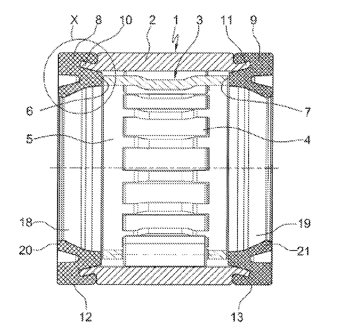
Needle sleeve, in particular for pivotably mounting the throttle valve shaft of a control device for recirculating exhaust gas in internal combustion engines
a control device and needle sleeve technology, which is applied in the direction of exhaust gas recirculation, non-fuel substance addition to fuel, bearings, etc., can solve the problems of increasing attack, propagating into the interior of the throttle valve bearing of such control devices, and correspondingly increasing the amount of exposure of the throttle valve bearing to increase the amount of exposure, so as to eliminate the production step of flanging and high efficiency. , the effect of economical production
Active Publication Date: 2013-12-26
SCHAEFFLER TECH AG & CO KG
View PDF0 Cites 2 Cited by
- Summary
- Abstract
- Description
- Claims
- Application Information
AI Technical Summary
Benefits of technology
The invention is a needle sleeve for use in internal combustion engines. The needle sleeve is designed to protect against corrosion caused by exhaust gas condensates while also being cost-effective to manufacture. It achieves this by using a rimless cylindrical outer ring and two lip sealing rings with an S-shaped profile that act as both seals and retain the needle roller and cage assembly. The needle sleeve is sealed statically to the housing and dynamically to prevent exhaust gas condensates from flowing through.
Problems solved by technology
In new generations of engines in the Euro 5 / US 7 emissions classes, however, it has been shown under long-term operating conditions that with increasing quantities of so-called blow-by gases, the throttle valve bearings of such control devices are exposed to correspondingly increased quantities of exhaust gas condensates that penetrate through the housing bores for the throttle valve shaft to the throttle valve bearings.
These exhaust gas condensates have an oily / watery to oily / acidic composition, so that the needle sleeves of the throttle valve bearings, which as a general rule are made of hardened ball and roller bearing steel with low alloying content and low carbon content, are initially subject to increased attack by external corrosion, which also propagates into their interior despite the multiple sealing of the throttle valve bearings.
As the corrosion progresses further, rust creep then takes place in the seals, resulting in damage and the failure of the throttle valve bearings in conjunction with functional failure of the throttle valve.
A first countermeasure, the avoidance of corrosion of the throttle valve bearings by a corrosion-reducing zinc-iron coating of the outer rings, for example using Corrotect®, has heretofore proven unsuitable, since the acid-bearing condensate of the exhaust gases dissolves the zinc-iron coating, and thus its sacrificial anodic action that provides the corrosion protection is lost.
Although another countermeasure, proposed in WO 2009 / 103,378 A1, to produce the needle sleeves of both throttle valve bearings from a high-alloy, corrosion-resistant sheet steel by deep-drawing without further heat and / or surface treatment, has indeed achieved the sought-after success, this measure has proven uneconomical on the whole because of the increased production and tooling costs required by such a material.
Method used
View moreImage
Smart ImageViewing Examples
Examples
first embodiment
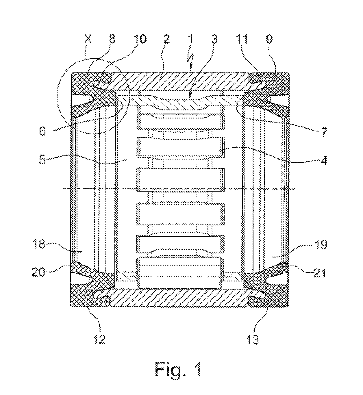
[0015]FIG. 1 a cross-section through the needle sleeve designed according to the invention;
second embodiment
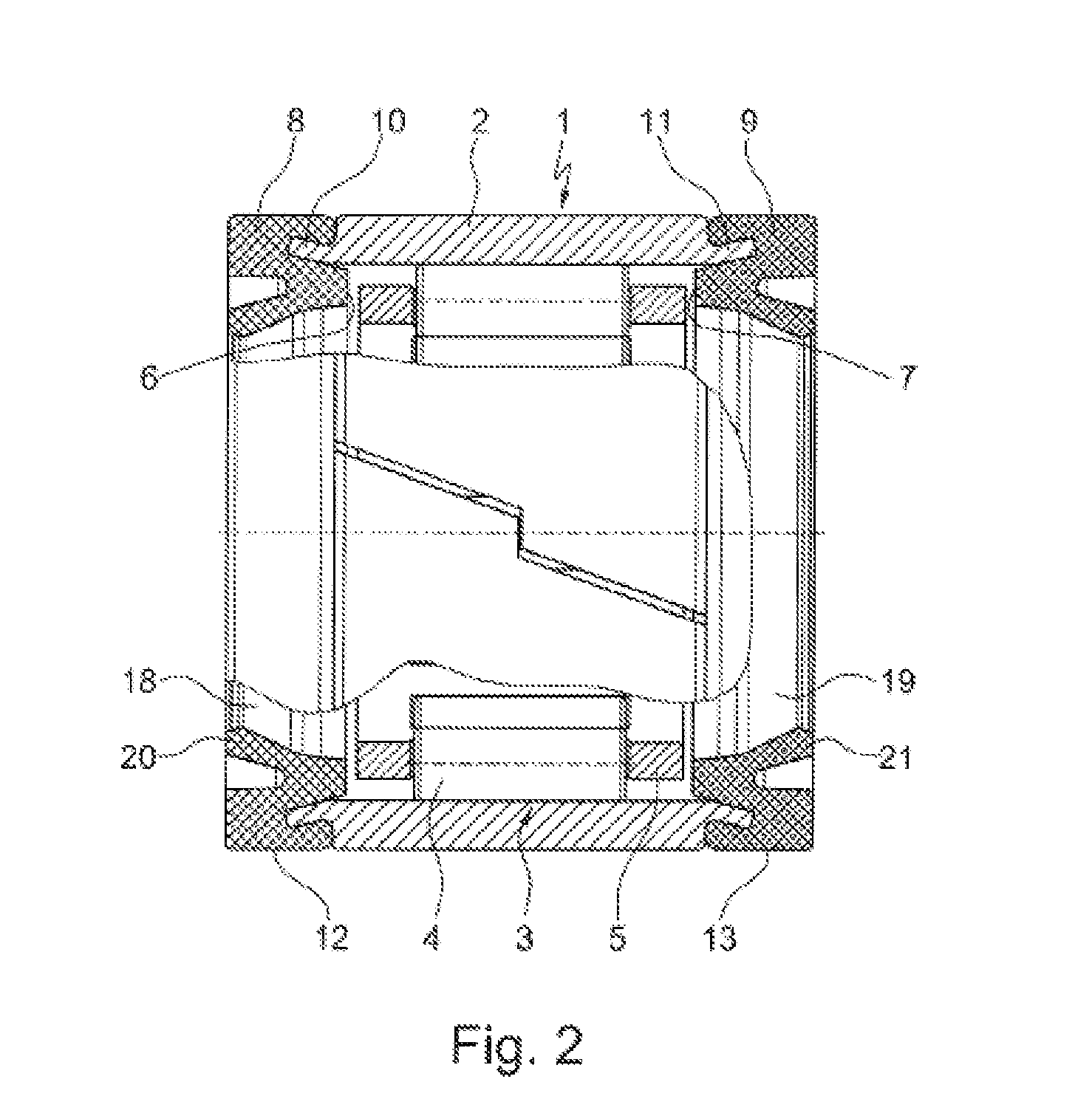
[0016]FIG. 2 a cross-section through the needle sleeve designed according to the invention;
[0017]FIG. 3 an enlarged view of the detail X from FIG. 1, with a first variant of a seal design;
[0018]FIG. 4 an enlarged view of the detail X from FIG. 1, with a second variant of a seal design.
Login to View More PUM
 Abstract
The invention concerns a needle sleeve (1), in particular for pivotably mounting the throttle valve shaft of a control device for recirculating exhaust gas in internal combustion engines, which consists primarily of a thin-walled outer ring (2) formed by non-cutting means and a needle roller and cage assembly (3) that is inserted in this outer ring (2) and is composed of a plurality of bearing needles (4) and a needle cage (5) that carries the bearing needles (4) at uniform spacings in the circumferential direction. The needle sleeve (1) has, at its axial sides, two radially inward facing ribs (6, 7) holding the needle roller and cage assembly (3) in the outer ring (2), and is designed with multiple seals (8, 9) by means of which the sleeve is sealed to prevent exhaust gas condensates from flowing through. According to the invention, the outer ring (2) of the needle sleeve (1) is designed as a rimless, cylindrical sleeve, while the seals (8, 9) of the needle sleeve (1) are composed of two lip sealing rings with an S-shaped cross-sectional profile that are located at least partially outside the outer ring (2) and are pressed onto its axial edges (10, 11), which sealing rings are at the same time implemented as radially inward facing ribs (6, 7) of the needle sleeve (1) that retain the needle roller and cage assembly (3) in the outer ring (2), and by means of which sealing rings the needle sleeve (1) can be sealed both statically to a housing enclosing it and dynamically to prevent exhaust gas condensates from flowing through.
Description
FIELD OF THE INVENTION [0001]The invention concerns a needle sleeve according to the generic features of claim 1, which is especially advantageously suitable for pivotably mounting the throttle valve shaft of a control device for exhaust gas recirculation in internal combustion engines.BACKGROUND OF THE INVENTION[0002]Exhaust gas recirculation in internal combustion engines is currently part of many engine concepts in order to meet prescribed emission limits, most notably in Europe. It serves to reduce nitrogen oxides in the combustion of fuels in gasoline and diesel engines in that a portion of the exhaust gases is deliberately conducted back to the combustion chamber of the internal combustion engine. At the present time, a distinction is made between two methods of exhaust gas recirculation in internal combustion engines, namely between internal exhaust gas recirculation by overlaps in the valve opening times by means of camshaft regulation or variable valve drives on the one han...
Claims
Login to View More Application Information
Patent Timeline
 IPC IPC(8): F02M25/07
CPCF02D9/106F02M25/0793F16C19/466F16C33/605F02M25/077F16K1/224F16K1/2268Y02T10/121F16C33/7809F02M26/52F02M26/70Y02T10/12
Inventor FICK, MATTHIASSCHAFERS, HEINZ
Owner SCHAEFFLER TECH AG & CO KG
Features
- R&D
- Intellectual Property
- Life Sciences
- Materials
- Tech Scout
- Unparalleled Data Quality
- Higher Quality Content
- 60% Fewer Hallucinations
Learn More Browse by: Latest US Patents, China's latest patents, Technical Efficacy Thesaurus, Application Domain, Technology Topic, Popular Technical Reports.
© 2025 PatSnap. All rights reserved.Legal|Privacy policy|Modern Slavery Act Transparency Statement|Sitemap|About US| Contact US: help@patsnap.com


